As an engineer, you know the gap between design and production is not simple. A part model might appear accurate on your CAD Design, but before it arrives at the workstation, you may experience delayed deliveries, erratic production, and inconsistent tolerances issues. These challenges become even more complicated when moving between small custom orders and larger production batches.
However, CNC metal lathes overcome these problems. It’s a viable solution to eliminate these challenges as these machines provide the precision your projects demand while keeping every part consistent and do not change a single part, whether it is a prototype or a large production lot.
You also have the benefit of reduced costs and lead times. Automation lowers material wastage, minimises labour and prolongs the lifespan of the machines. For engineers working across custom parts and large runs, a CNC lathe is one tool that keeps production steady.
What is a CNC Metal Lathe?
A CNC metal lathe precisely shapes and cuts through metal parts with exceptional precision. The operation is similar in principle to a conventional lathe, whereby the material is held fast and is rotated with the removal of material by a tool. The only difference is that a computer program operates the entire process, and no operator or manual intervention is needed. This allows the repetition of each cut, movement, and dimension without any error, no matter how many parts are created.
The machine takes instructions in the form of G-code, either written or generated based on CAD designs. Code is converted into a readable digital notation using CAM and instructs the lathe on the speed of rotation, depth, and the route to follow by the tool. Since the program drives the tool and creates the shapes that are too time-consuming or difficult to create manually, such shapes can be made within a minimal time. This also entails no variation between the parts, which is essential for tight tolerances.
Moreover, they save time, generate low waste, and facilitate rapid change-overs between jobs without disassembling the machine. With only a new program to load, changing the parts takes little time. It is suitable whether the job is a prototype or a thousand-part run. This combination of dependability and adaptability makes them a standard tool in industries like aerospace, automotive, medical, and energy.
A Brief History of CNC Metal Lathes
CNC lathes were developed due to the high precision and speed requirements. Manual lathes depended on the operator’s expertise, and mistakes often occurred. With the development of the industries, there was more demand for precise and repeatable machining. This requirement paved the way for numerical control.
The initial types were made in the early 1940s and 1950s. The aerospace firms required closer tolerances and quicker production of parts. Punch cards were used to direct tool paths found by engineers. This eliminated human error and ensured that parts had the same cut.
John T. Parsons and Frank L. were key pioneers of this enhancement. Stulen invented earlier aircraft manufacturing systems. Their effort showed that machines could take preprogrammed instructions. Subsequently, with the development of computers, numerical control became completely digital. This change brought about the CNC lathe that is being used today in modern facilities.
How Does a CNC Metal Lathe Machine Work? Step-By-Step
As mentioned before, a CNC lathe operates by removing material from a workpiece. No manual input is needed in the process, but rather is controlled by programmed instructions. All steps are designed to reach precision and repeatability.
The material is rotated in the machine at the right speeds. Cutting tools are pressed along with preset paths to cut the workpiece. This pairing provides parts to meet tight tolerance design requirements. The following are the key steps that describe how a CNC lathe works.
Workpiece Loading
The initial stage is loading the raw material. The bar or block is firmly fastened into the lathe chuck. Optimal clamping eliminates vibration and gives stable machining. Before starting, operators check to ascertain alignment. Accuracy can be interfered with by even minor misplacements. The machine can go with the programmed cycle when in the correct position.
Setting Up the Programme
The second step is programming the machine. Engineers add information on the design using CAD and CAM software. The programme specifies paths of cutting, speeds, and tool change. This digital control abolishes the manual guesswork. The instructions give the machine the specifications of what it should do. When the programme is in place, production becomes consistent and repeatable.
Machining The Part
The third step is the actual part cutting. The workpiece is rotated at programmed speeds by the spindle. Cutting tools travel in an X and Z direction to cut the material. Coolant coating is used to cool the tool and prolong its life span. This goes on until the part fits the CAD design.
Monitoring the Operation
Although machining is automatic, it must still be monitored. Operators inspect tool wear, spindle loads, and vibrations. Temperature and tool position sensors are also used to observe issues.
In case of problems, they are corrected right away. Also, closely monitoring eliminates scrap and machine wastage. This keeps the process in check.
Finishing and Inspection
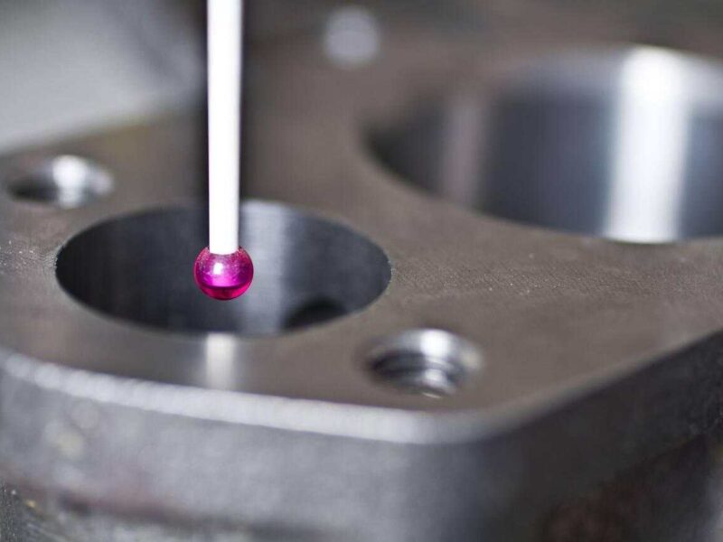
The last step is finishing and checking. The dimensions and tolerances are verified by measuring the part dimensions using callipers and CMM machines. The surface finish is checked for smoothness and defects.
If the part fits the requirements, it is sent to the next production stage. Otherwise, there is correction, and re-machining may follow. This prevents incorrect parts from being made for assembly.
What are the Core Components of a CNC Metal Lathe Machine?
A CNC lathe is constructed around several key components. Each serves a specific purpose and aids precise machining. It would not be possible to cut accurately and repeatably in their absence.
These parts are in harmony to give stability, mobility, and command. Combining these makes the machine cut metals under stringent tolerances. The machine’s performance is directly dependent on the quality of the parts. The significant parts of a CNC lathe are given below. Each describes the purpose of such a section and its technical significance.
Bed
The bed supports all essential assemblies in the correct position. A firm bed eliminates vibration when it comes to cutting. The majority of CNC beds are cast out of quality iron. This material is used to impart strength, stability, and thermal resistance. A well-designed bed helps to ensure long-term accuracy.
Headstock
The main spindle and its drive are in the headstock. It supplies the rotational power required to rotate the workpiece. Torque and speed are transmitted through this unit.
Contemporary headstocks have servo or variable-speed motors. This enables speed control when working with different materials. The headstock is strong enough to handle both light and heavy cuts.
Spindle
The spindle is the center shaft inside the headstock. It holds and rotates the workpiece with high precision. Spindle runout has a direct influence on tolerance and part surface finish quality.
CNC spindles employ accurate angular contact bearings. These allow high-speed operations to be conducted with stability. A balanced spindle will extend tool life and lower the heat.
Chuck
The chuck clamps the job material firmly in the machining process. It can either have three, four, or collet jaws. The type is based on part shape and size.
CNC systems commonly use hydraulic chucks. They have a constant clamping load and quicker loading. This promotes safety and reduces the setup time.
Turret
The turret contains and indexes the cutting tools. It spins every tool to the position. This facilitates several functions in one installation. Servo drives are commonly used on CNC turrets to provide rapid indexing. They carry turning, boring, threading, and grooving tools. The system minimizes downtimes and improves productivity.
Tailstock
The tailstock aids long and slender workpieces. It eliminates deflection as the part rotates at speed. The unit glides on the bed regarding positioning.
Many tailstocks feature a quill to be used during drilling. This provides flexibility without repositioning of the workpiece. It is essential for shaft and bar machining.
Carriage
The carriage traverses the tools following pre-programmed axes. It regulates the depth of cut and the tool feed. Fluid motion brings precise machining contours.
The carriage is moved by means of ball screws and linear guides. Such systems lower friction and resist wear over a long period of time. Repeatable precision is enabled by stable carriage motion.n
Control Panel
The operator interface shows programs, machine status, and error codes. Operators utilise it to operate and tune up operations. The contemporary panels have touchscreen and CNC software. They allow fast editing and sophisticated diagnostics and increase efficiency compared to traditional ones.
Cooling System
The cooling system controls heat in the cutting process. It sprays coolant to the workpiece and tool. This causes less tool wear and also enhances surface finish.
Coolant also removes chips from the cutting area. Pumps, nozzles, and filtration units keep flow consistent. Cooling increases the life span of a machine or tool.
Chip Management
Chip management handles swarf generated during machining. It eliminates waste quickly to avoid clogging and damage to tools. CNC lathes frequently have conveyors and chip augers. These transfer chips to bins that are placed outside to be collected. Good chip handling leaves machining areas clear and safe.
What Types of CNC Metal Lathes Are Available?
CNC lathes come in various arrangements, each optimised to a set of machining requirements. The right pick is based on the type of material, the dimensional tolerance, and the volume desired. The engineers should consider spindle orientation, axis possibilities, and the workholding technique before choosing a machine.
Modern lathes are very versatile. Some models are programmed to perform simple turning, while others embrace live tooling to perform milling. The correct decision is a trade-off between cost, throughput, and part complexity.
Two Axis CNC Lathe
A two-axis lathe performs only on the x and z movements. The spindle rotates the component, and a turret centres the tool. This design is capable of turning, facing, drilling, and threading.
They are apt to use cylindrically shaped parts with medium tolerances. Typical applications involve shafts, fasteners, and pipe fittings. They are still very economical in batch production and general-purpose machining.
Typically, tooling is used in the form of indexable carbide inserts. Workholding is dependent on the use of chucks, collets, or centres. Usually, operators choose these machines for turning materials such as mild steel, aluminium, and brass.
Multi-Axis CNC Lathe
Multi-axis machines give additional control of 3, 4, or 5 axes. The more sophisticated models can combine turning and complete milling. They integrate Y-axis travel, sub spindles, and live tooling.
These machines can deal with intricate geometries in one setup. This increases throughput, enhances part precision, and eliminates human intervention. Generally, these are applied in the aerospace and defence industries for making turbine blades and missile housings.
CAM programming is more elaborate and needs CAM software to generate the toolpaths. The machine’s rigidity and thermal stability are essential to maintain micron tolerance.
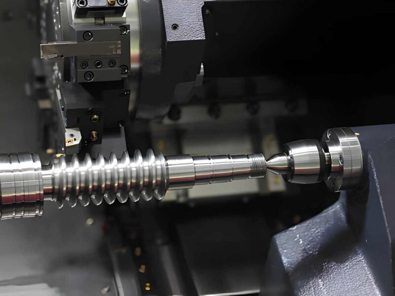
Swiss-Type CNC Turning Lathe
A sliding headstock and guide bushing are used on a Swiss lathe. The bushing holds the workpiece near the cutting. This avoids deflection during the machining of long and slender parts.
These are multiple spindle machines and live tooling units. They frequently accommodate as many as 10 axes, simultaneously allowing turning, milling, and cross-drilling. They offer short cycle times due to overlapping operations.
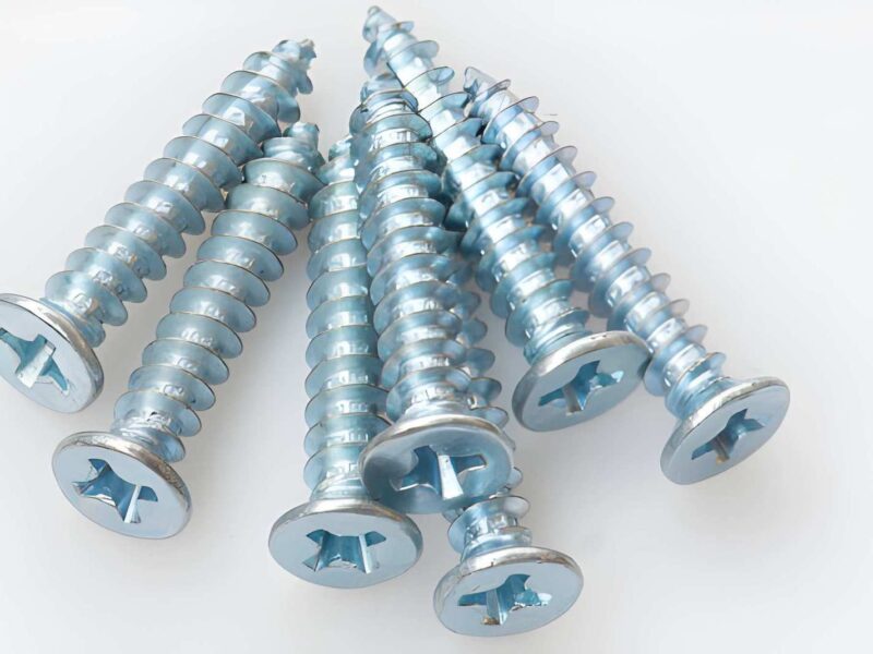
Medical screws, watch components, and miniature connectors are examples of applications. The high-volume production, where precision and repeatability of the work are the key aspects, makes the Swiss lathes the most competitive. Usual materials are stainless steel, titanium, and special alloys.
Vertical CNC Turner
Vertical CNC lathes have the spindle vertically mounted. The piece is placed on a big face plate or table held by gravity. This arrangement is excellent in the support of heavy parts.
The machines are applicable for large diameters and short lengths. Brake discs, turbine housing, and rings are standard components. The stiffness of the construction makes it immune to vibration when cutting deep passes are made.
Cutting forces are towards the bottom, which enhances the tool life and surface finish. Nevertheless, they need more space on the floor and slower stages of workpiece loading.
CNC Lathe Horizontal
Horizontal lathes are still industry standard in terms of multifunctionality. The spindle is aligned parallel to the machine bed so that gravity can aid chip evacuations. This maintains a cutting zone free of obstructions and minimises tool wear.
These machines handle many parts, both small pins and large shafts. They are used on several turrets and tailstocks on longer workpieces. Higher-end models include sub-spindles to transfer parts.
They are common in automotive, oil and gas, and heavy equipment industries. The materials that can be machined range from aluminium to Inconel using the appropriate tooling.
Comparison of CNC Lathe Types
| Lathe Type | Axis Capability | Workholding Method | Typical Part Size | Ideal Materials | Pros | Cons |
| Two-Axis | X, Z only | Chuck, collet, centres | Small–medium | Steel, aluminium, brass | Affordable, simple operation | Limited part complexity |
| Multi-Axis | 3–5+ axes | Chuck, sub-spindle | Small–large | Steel alloys, titanium, and composites | Complex parts in one setup | High cost, complex programming |
| Swiss-Type | Up to 10 axes | Guide bushing, collet | Very small, slender | Stainless steel, titanium, superalloys | High precision, fast cycles | Limited to small parts |
| Vertical CNC | 2–5 axes | Faceplate, table | Large, heavy | Cast iron, steel, alloys | Rigid, handles massive parts | Large footprint, slower handling |
| Horizontal CNC | 2–4 axes | Chuck, centres, tailstock | Small–large | Wide range | Versatile, efficient chip removal | Less suited for oversized parts |
What Operations Can Be Performed on a CNC Metal Lathe?
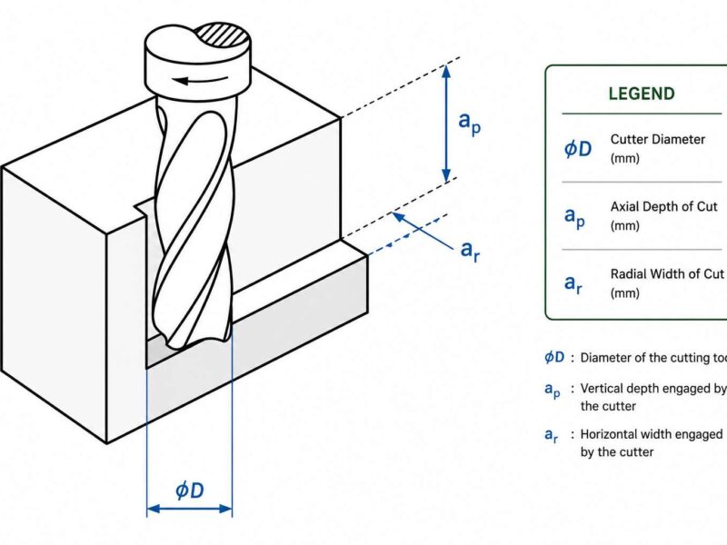
- Turning: Turning cuts away the material on the circumference of the workpiece. The tool is driven along the axis to attain the desired diameter. It is applied to create straight, conical, or contoured surfaces. Turned parts have a tolerance of +/- 0.01 mm and a surface finish of Ra 0.8 microns.
- Facing: It cuts the material off the end of the work. The tool traverses along an axis that is perpendicular to the surfaces generated. It can be used to square bar stock, as a surface conditioner before drilling, or to shorten the length. Facing operations also improve surface flatness before post-machining.
- Thread Cutting: Cutting a thread converts external and internal threads with accurate pitch control. The CNC programme coordinates the spindle with the tool movement. Metric and imperial threads may be cut, e.g., complex trapezoidal and multi-start threads. CNC control provides repeatability of within +/-0.01 mm.
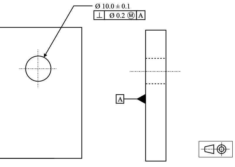
- Drilling, Boring: During drilling, holes are generated along the axis using static or live tools. Boring enlarges holes previously drilled to produce tighter tolerances and improve fits. These operations utilise boring bars, indexable or reamers. The standard boring reach tolerance is +/- 0.005mm, critical for aerospace and hydraulic components.
- Grooving and Parting: Grooving creates recesses or reliefs at prescribed diameters or shoulders. Separating the finished part and the bar stock is done by parting. Insert tooling is stability-oriented and chip-evacuation oriented. Grooving may be either internal, external, or face-oriented. Parting is a rigid setting up to avoid tool breakages.
- Knurling: Knurling transfers a patterned feel to the surface of the workpiece. It enhances the holding of parts like fasteners or handles. The CNC control ensures the consistency of the pattern pitch and depth along the diameter. Knurling wheels are used in cross, straight, or diamond patterns.
What are G-Codes and M-Codes in CNC Metal Lathe?
G-Codes
G-codes control the motion of the CNC metal lathe. They define positioning, cutting cycles, and tool movement. Here are the common examples of G-codes and their functions.
- G00: Rapid positioning
- G01: Linear interpolation (cutting move)
- G02/G03: Circular interpolation (clockwise/counterclockwise)
- G28: Machine home return
- G96: Constant surface speed
Note: These codes tell the lathe how the tool should move in relation to the workpiece.
M-Codes
M-codes handle machine functions that are not related to movement. They switch actions on or off. Their common examples include:
- M03: Spindle on (clockwise)
- M04: Spindle on (counterclockwise)
- M05: Spindle stop
- M06: Tool change
- M08: Coolant on
- M09: Coolant off
- M30: Program end and reset
M-codes act as machine commands, while G-codes act as path commands. Both work together to execute precise turning operations.
Common Software Used in CNC Metal Lathe Programming and Machining
- Mastercam
- Fusion 360
- SolidCAM
- Edgecam
- GibbsCAM
- Esprit CAM
- PowerMill
- HSMWorks
- CATIA
- NX CAM
- HyperMill
- CAMWorks
- Vericut
- SprutCAM
- FeatureCAM
Final Verdict!
CNC metal lathes are becoming inevitable in machining. They are highly accurate and repeatable, which cannot be obtained by any manual method. These make the results reliable and costs anticipated, whether it is custom parts or entire production runs.
But all machining processes are distinct. Turning at a high speed is most effective with small, precise components. Larger machine shafts and industrial parts require heavy-duty turning. Multi-axis turning is appropriate when you have to shift between custom and batch production.
It is why we choose a CNC metal lathe, not necessarily the machinery itself we are choosing, but rather how it is integrated into your process. Learning these differences, you will be able to select an option that fits your project’s demands and goals. The right CNC metal lathe will facilitate higher quality, speedy delivery, and efficient production.
FAQ’s
Q1. What is CNC turning used for?
CNC turning is used to shape round, cylindrical, and symmetrical parts. It is best to make shafts, pins, bushings, and threaded components. It has widespread use across industries such as automotive, aerospace, and medical.
Q2. How is CNC turning different from milling?
Turning rotates the workpiece while the cutting tool stays still. Milling does the opposite. The tool moves while the part is fixed. Turning is best for round shapes and symmetrical designs; on the other hand, milling handles flat surfaces and complex geometries.
Q3. Which turning process should I choose for my project?
It depends on your part design and volume. High-speed turning suits small and detailed parts. Heavy-duty turning is better for larger and stronger materials. If you handle both custom and batch runs, a multi-axis turning set-up is a go-to option.