While the world has made reasonable advancements in CAD model data, engineering drawings are still one of the most integral parts of design and manufacturing. Project by project, 2D drawings are still desperately needed to convey important information in drawings. This is to ensure that all the information required is properly captured and that the design intent for CNC machining is accurately communicated.
Engineering drawings are also very powerful as they serve as legally binding documents. This is why machine shops will generally spend more time quoting drawings with pronounced callouts, tolerances, and features. The price of these types of projects is also expected to be on the upside due to the extra time and effort required in inspecting and ensuring that the final part meets specifications.
Having emphasized the importance of engineering drawings, there are a number of things to keep in mind to avoid providing a drawing that will actually make your quote less affordable and extend production lead times. The following tips will help you know what, how, and whatnot to include to help you communicate clearly and effectively.
1. Create a Drawing Checklist
 Drawing Checklist
Image Description: A drawing checklist showing key points to review for accuracy, dimensions, and completeness in technical drawings.
Depending on what type of phase of the project you are working on, having a checklist for each drawing can help you stay abreast of what has or hasn’t been captured. The checklist for drawing your product concept can be different from that of the prototype and final product drawings.
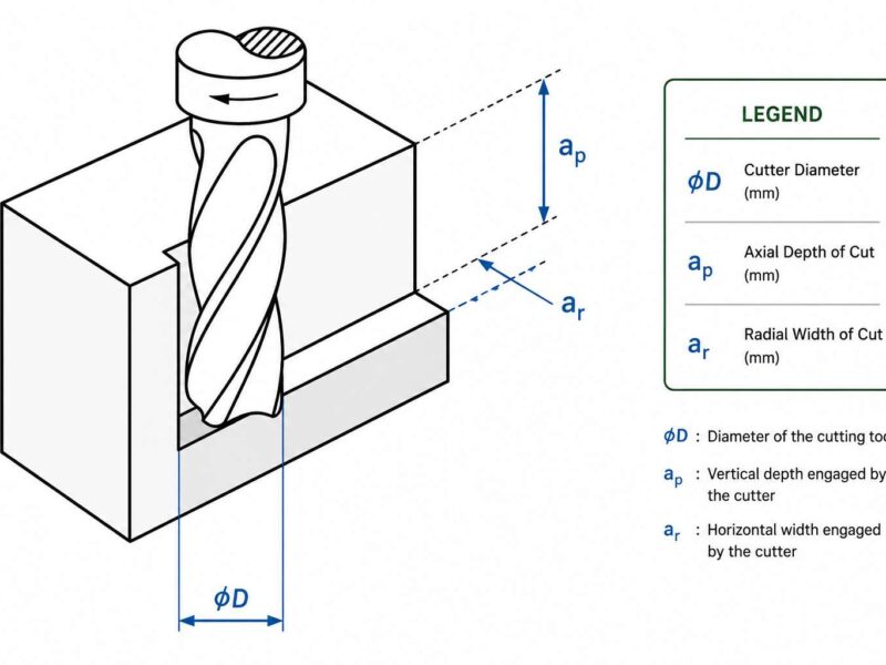
2. Use Good Drafting Standards
Good line work is essential for creating clear, professional technical drawings. You need to use different line thicknesses to show what’s important. Use thick lines (0.7-0.9mm) for the main outlines and where things are cut, medium lines (0.5mm) for edges you can see, and thin lines (0.3mm) for dimensions and hatching. Once you pick a thickness for a specific purpose, stick with it throughout the entire drawing. Your lines should be solid and clean, without any breaks or messy overlaps. Make sure they’re dark enough to see clearly and maintain the same thickness from start to finish. Sloppy, uneven lines make your work look unprofessional. Use the right tools for the job, take your time, and keep your pens or pencils in good condition so your lines stay sharp and visible, even when the drawing gets printed or shared digitally. Following established standards like ISO 128 or ASME Y14.2 helps ensure your drawings meet professional expectations and can be easily understood by anyone who reads them.
3. Do Not Bury the Reviewer with Details
Try to limit the drawing to only enough detail for the current scope or purpose of work. For instance, the details that should be included in a concept should be different from those in an issue for bid or a total design review.
4. Dimension-only Important Features
We advise that you only include dimensions for critical and quantifiable features, as all dimensions can be obtained from the product’s 3D model. For your 2D drawings, only include dimensions that can be measured using hand tools like rulers, micrometers, calipers, and the like. Typically, your drawing should consist of depth, bore diameters, and parallel inside and outside dimensions. Including dimensions for radii between surfaces, hole to center, or edge distances will simply expend more time and effort.
5. Ensure that All Drawings have the Same Building Orientation
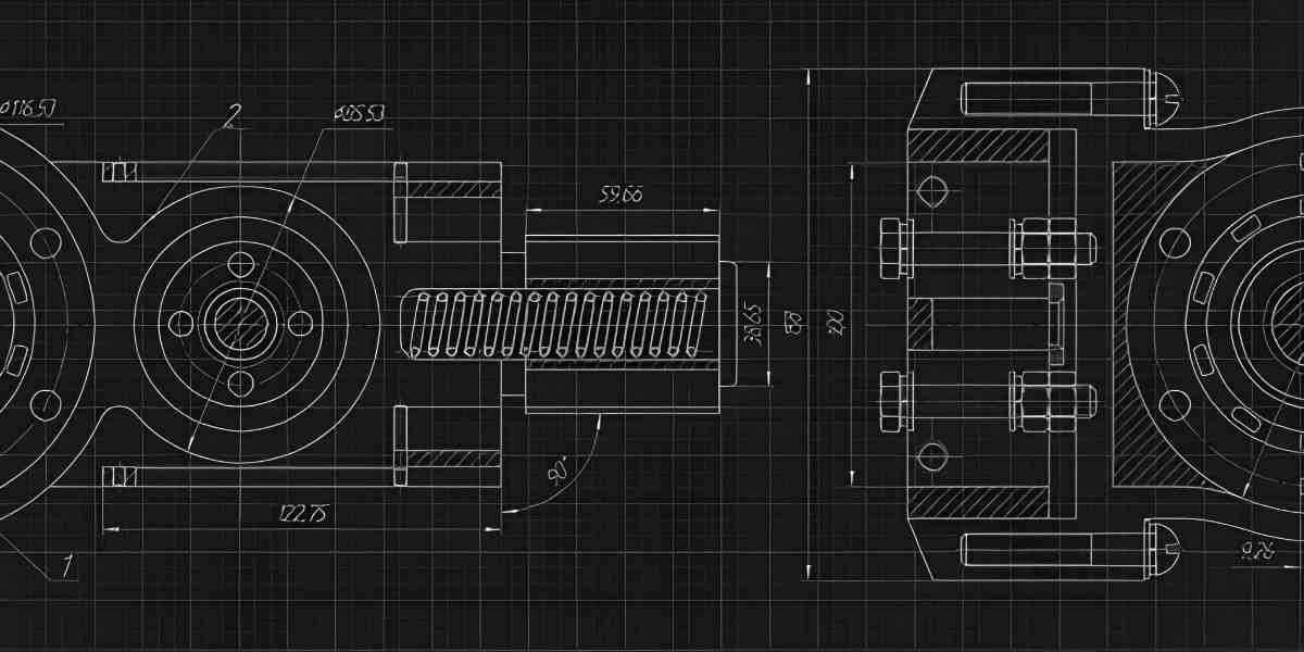 Technical Drawing
Image Description: A technical drawing displaying detailed dimensions and views of a mechanical component for manufacturing.
Keep the same building orientation across all your drawings so people don’t get confused when comparing different views. If the building faces north in the site plan, make sure it faces the same direction in floor plans, elevations, and sections. This consistency helps viewers understand how everything relates to each other and makes your drawing set much easier to read and navigate.
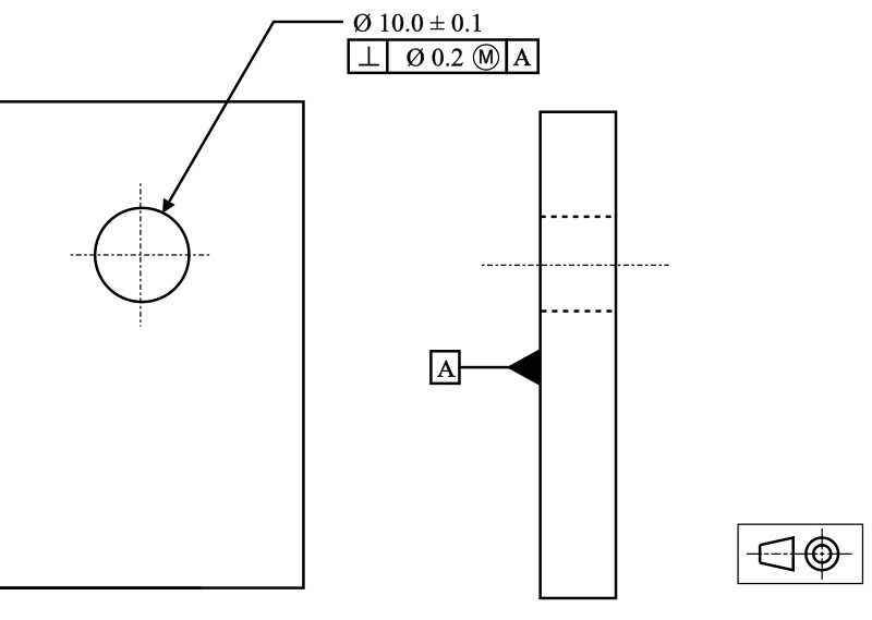
6. Add Callouts to Improve Clarity and Understanding
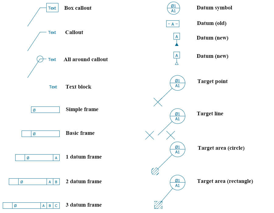 Engineering Drawing Callouts
Image Description: An image showing engineering callouts highlighting specific dimensions, features, and notes for manufacturing guidance.
Avoid leaving features to “experience” or “chance”, presuming the machinist would understand. Also, when dealing with designs that have multiple instances of callouts, use a numbering system to denote them. For instance, 5×10-35 TAP to show 5 threaded holes. This will help you save time and redundancy.
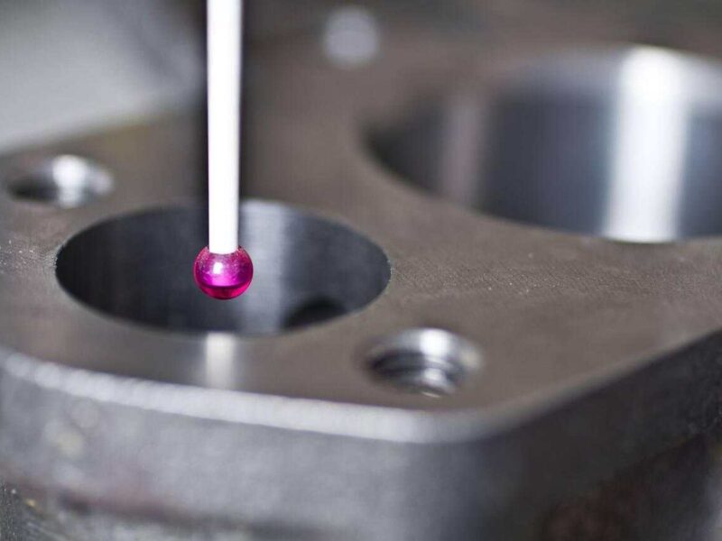
7. Keep your Tolerances within the Capabilities of Hand Metrology Tools
You can avoid extra costs by ensuring that your tolerances stay within the possibilities of common hand tools such as calipers, rulers, and micrometers. This is because the additional effort to meet these tolerances will translate into more labor, time, and, consequently, cost.
8. Avoid Over-dimensioning and Over-tolerance in Your Design
Ensure that all dimensions are done towards one location and remain properly referenced to their relevant details and sections. This way, any changes will be easier to make rather than changing in several instances. In the design, it is noteworthy that only a couple of features are critical to the part’s function. Over-dimensioning may prevent the machinist from losing sight of what is essential, and overuse of tolerances will drive up the cost of the product.
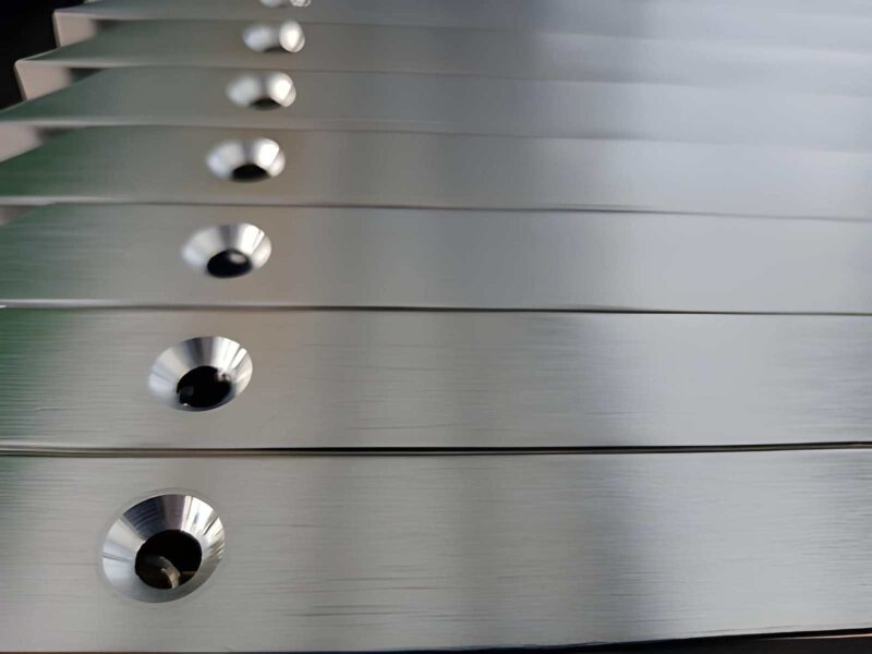
9. Avoiding Costly Production Errors
Engineering drawings are the foundation of quality prototyping and part production. Avoid costly production errors by working with the right manufacturing company in China.
At Premium Parts, our engineers will comply with the engineering drawings given, dig into every dimension and tolerance with proper manufacturing technology to make parts within the client’s expectations.