It doesn’t matter whether you are building a prototype or producing many parts; CNC machining takes a long lead-up before starting. Everything starts with a CAD file.
The driving force behind CNC machining is CAD files. These files aren’t intended as simple blueprints, but as the key way for designers and machinists to interact. Even some of the most sophisticated designs will struggle in production if they use the wrong file format or do not have a correctly shaped model.
At Premium Parts, it is clear to us from our client work with startups, engineers, and large-scale manufacturers that delay or excess spending often comes from not knowing the right file formats to use before starting the project. Proper knowledge of CAD files helps make the CNC process quick, accurate, and cheaper.
We’ll cover what CAD files are, the main formats important for CNC machining, and how to pick the best option for your manufacturing job. No matter your level of experience, this guide will point out how to avoid frequent design mistakes and boost your models’ productivity in the actual workspace.
What Is a CAD File?
A CAD file is a digital picture of a part or product. All the key information on shape, features, and size is found in the CAD file, which is used in today’s manufacturing.
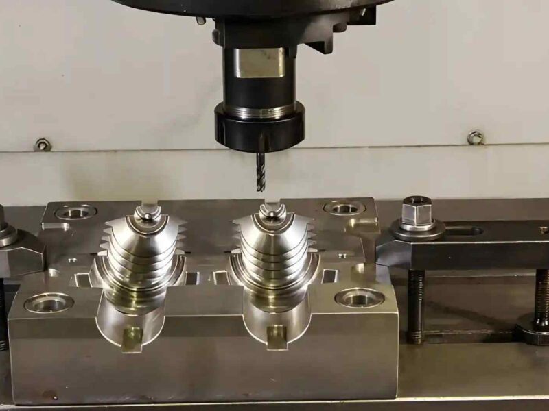
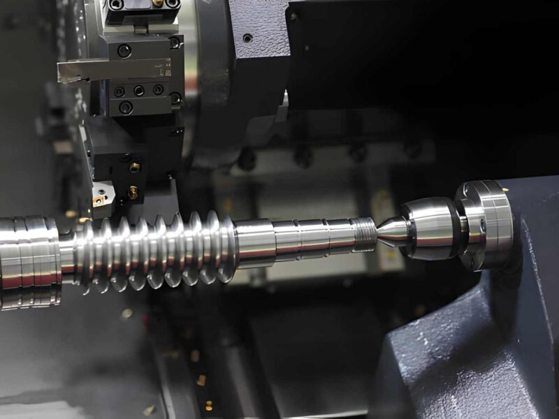
A CAD file can be drawn in either two or three dimensions. Normal 2D CAD files describe flat outlines, which are used for cutting with lasers or plasmas. Since 3D CAD files display both depth and volume, they are essential for CNC milling, turning, and many other kinds of subtractive manufacturing.
CAD is most valuable for its ability to create accurate work. Thanks to these files, engineers can design models that fit all required measurements and tolerances. After the CAD file is given to machinists, it serves as an instruction manual showing how to shape, drill, mill, or finish the part.
How CAD Files Interact with CNC Machining
Things don’t stop after you make your CAD file; there are other steps to take. When the CAD model is acquired, it needs to be understood and converted into machine-interpretable guidelines. It is during this phase, from design to reality, that both precision and compatibility matter the most.
Here’s a look at how the process works:
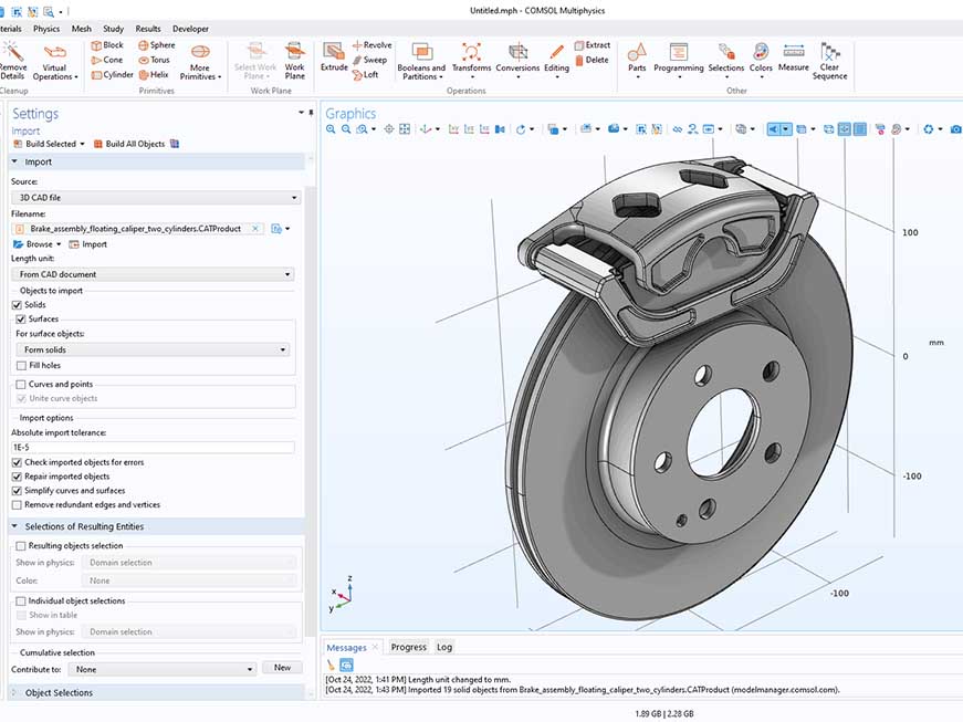
- You bring your 3D CAD model into CAM (Computer-Aided Manufacturing) software. At this stage, a computer creates toolpaths that your cutting tools will use according to your part’s design.
- Once you set the process parameters in CAM, the software turns them into G-code. CNC machines only understand this kind of language.
- After reading each G-code line, the CNC machine executes the order-cutting, drilling, or shaping to build the final part from your material.
What is most important to remember? A fully prepared CAD file supports a continuous product flow. Misspelled data, missing information, or files with problems can interrupt work and cause errors.
Common CAD File Formats Used in CNC Machining
CAD files are not all made the same. Using an improper file format may result in unnecessary delays, conversion problems, or errors in manufacturing. The following are the main CAD file formats in use for CNC machining, plus their strengths, weaknesses, and applicable CAD software.
1. STEP (.stp /.step)
STEP is considered the most commonly used 3D CAD file format for CNC machining. It helps keep parts, surfaces, and assemblies intact as a neutral format. It helps CAD/CAM tools interact smoothly with each other and with various machines. Translates with a high level of accuracy.
It is compatible with SolidWorks, Fusion 360, Siemens NX, CATIA, Creo, Inventor, Mastercam, and most modern CAM tools.
It’s the best choice for machining.
2. IGES (.igs / .iges)
Previously, IGES was widely used for neutral files carrying wireframe, surface, and solid information. Although it is STEP, it is still found in a lot of common workflows. It makes it easier to use geometric information from one app to another. Yet, it does not have some of the strong features that STEP includes.
It is compatible with AutoCAD, SolidWorks, Creo, CATIA, Fusion 360, Rhino, and a number of other software applications.
It is only a good choice for basic parts or old legacy files.
3. STL (.stl)
STL files consist of a mesh of triangles, which were initially used for 3D printing. They outline the shape of a part, yet do not provide information such as size or what it’s built from. It’s useful for quick 3D printing or visualization, but it’s not precise enough for CNC.
It is compatible with Blender, Fusion 360, MeshLab, SolidWorks, Cura, and various slicers for 3D printing.
It is not recommended for CNC.
4. DXF (.dxf)
A 2D format that people often use for laser cutting, waterjet cutting, and CNC routing. It describes the outline and contours. It doesn’t describe depth. Cutting flat patterns is easy, especially with cutting sheet metal or making signs.
It is compatible with AutoCAD, SolidWorks, DraftSight, CorelDRAW, Adobe Illustrator (using plugins), and many programs for laser cutting.
It is a great choice for 2D cutting applications.
5. DWG (.dwg)
DWG files are the standard AutoCAD format and carry both 2D and some 3D drawings. It is commonly used in architectural and mechanical drafts. Though widely used in 2D design, it usually must be teamed with additional notes or turned into a format for manufacturing.
It is compatible with AutoCAD, BricsCAD, DraftSight, SolidWorks (import), Fusion 360, and several other applications.
It requires conversion for CNC.
6. Native CAD Files (.sldprt, .prt, .ipt, etc.)
These files are unique to each CAD program and hold the full records, arrangement settings, and confidential details of a design. It is useful when a manufacturer shares the same CAD program with their partners. Sharing the files beyond the ecosystem may bring up several obstacles.
Compatible with:
- sldprt – SolidWorks
- .prt – PTC Creo, NX
- .ipt – Autodesk Inventor
- .f3d – Fusion 360
- .CATPart – CATIA
It is useful if the manufacturer supports the same software.
Which File Format Should You Use?
Your choice of file format affects how well your part will turn out, how smoothly and quickly it is created, and what expenses may be involved.
If you aren’t sure what format to use, STEP (.stp) should be your go-to. It is the format most trusted and supported in today’s manufacturing systems. Because STEP files include solid models, surface details, and assembly plans, they are easy to use for machinists.
Don’t use STL files for CNC cuts unless you must. Although they are suitable for quick reveals and 3D outputs, their mesh is not exact for machining composites by subtraction. STL files may create imperfections on the surface and may have to be addressed with additional procedures.
Sometimes, it can help to share files in SolidWorks (.sldprt) or Inventor (.ipt) format when you’re working with a manufacturer using similar software. Still, using formats connected to one program can make it harder when your supplier manages files in other CAM platforms.
Here’s a quick cheat sheet:
| Format | Use Case | Recommended? |
|---|---|---|
| STEP (.stp) | 3D machining | Yes |
| IGES (.igs) | Legacy models, simple parts | With caution |
| STL (.stl) | 3D printing | Not for machining |
| DXF (.dxf) | 2D cutting (laser/waterjet) | For profiles |
| DWG (.dwg) | 2D drawings | Needs conversion |
| Native CAD | Platform-specific work | If compatible |
Why Some File Formats Fail in CNC Machining
Picking the wrong CAD file format is more than a headache for milling. It can impact every aspect of the operation. There are file types that simply are not designed for the intense demands of CNC manufacturing.
Most times, we find the following problems in unsupported and badly structured files:
1. Missing Solid Geometry
Usually, STL formats and badly generated IGES files have at least one missing solid body. Generating toolpaths in CNC machines is only accurate if there is a solid 3D model. Because of this, cutting programs CAM is likely to be incorrect, which causes either delays or requires rejection of parts.
2. Lack of Tolerancing and Feature Definitions
The majority of formats ignore tolerances, threads, surface textures, and references to holes in a design. The absence of data leads the machinist to estimate rather than measure, which reduces how fast they can work and increases the risk of errors.
3. Conversion Errors
When conversion is done between programs that cannot handle each other’s data (like DWG to CAM), some details may be lost, or the shaped geometry may become blurry. Small issues in the design can result in real problems with the finished product.
4. Poor Mesh Quality
STL files and, in particular, those with a low resolution, lead to steps and ridges that are not true curves. That is unacceptable when precision machining is the method, as even surfaces play a key role in how well the piece functions.
How to Prepare CAD Files for CNC Machining
Furnishing your CAD document for CNC machining is about helping the raw material be cut away to match your drawing. If you plan well from the beginning, you’ll see fewer unforeseen problems during production.
Check out these guidelines to make your CAD file ready for machining:
1. Design for Manufacturability (DFM)
Remember to design your part for manufacture on a CNC machine. Do not create pockets that are too deep inside, excessively thin walls, or areas that standard tools won’t reach.
2. Pick the Right File Format
Exporting your 3D models as STEP files in the .stp format will help others use them more easily. While using this format, solid geometry, feature, and assembly information are stored accurately with a minimum loss of data.
3. Specify Critical Features
Make sure critical values such as tolerances, surface finishes, and threads are clearly labeled—add them if they cannot be understood from the shape of the part. They can be shown as annotations or added as another PDF file with separate drawings.
4. Orient the Part Properly
Place your model’s logical origin and reference plane in a logical position. Thanks to this method, programmers spend less time programming and less time setting up the machine.
5. Simplify Assemblies
If you’re preparing an assembly, set aside the parts that must be machined. Don’t add the whole multi-body assembly to the design unless you need to for clarity.
6. Finally, Double-Check
Use the verification features in your CAD software to identify errors, spaces, or problems in parts coming together. Smoother production with fewer problems is possible if the solid is clean and closed.
Best Practices for Sending CAD Files to Manufacturers
The way you share your CAD file with the manufacturing company is as important as preparing the file. Having smooth communication and proper handoffs makes production better.
Here’s what you can do to avoid any hurdles in getting your CAD files to the shop floor:
- Combine all your CAD models, drawings, and support documents (PDFs and so on) into a single ZIP folder. Give your work files easy-to-see titles so they don’t get lost.
- It is smart to supply a 2D drawing or PDF, explaining tolerances, types of materials, how surfaces should look, and any detailed instructions, along with 3D files. As a result, machinists have no doubts and can handle each task in order of priority.
- When working with large files, don’t rely on email. It’s better to put files onto secure portals like Google Drive, Dropbox, or WeTransfer, rather than sending them through email.
- Add the engineer or project manager’s contact details in case members of the manufacturing team require answers. It only takes a short confirmation to save a lot of revision time.
- Should your supplier support file checking or DFM advice, make use of it. Because we know it is better to avoid a problem rather than fix it.
At Premium Parts, we offer free file validation for all projects.
Prioritizing these practices takes out hassles and boosts the speed and accuracy of your manufacturing process.
The Role of CAM Software and G-code
Just because the CAD file is finished doesn’t mean the part is ready for the CNC machine. There’s a crucial stage in between: Computer-Aided Manufacturing. The design created on the computer is made real by G-code, which controls the motions of the machine.
For each element in the model, CAM software sets the steps for making it with a machine. The computer generates toolpaths that tell each tool how to move for every machine operation—from drilling and milling to turning and pocketing.
They are then changed into G-code, a computer language that CNC machines read piece by piece to guarantee very precise results.
Why it’s important:
A flawless design in CAD won’t work if the CAM setup is not correct. The outcome depends on the tools you use, the speed at which you feed the material, how deep your cut is, and the part’s initial orientation. The gap between what’s drawn on paper and what’s used in reality must be bridged correctly using CAM.
Partnering with a CNC company that recognizes both your design and their machine operations makes a big difference. They will identify the areas where toolpaths are inefficient and reduce the material you’re using to help your part be made exactly right.
If your CAD file is correct and your CAM setup is good, the G-code guiding production will give you the best results.
Your CNC File-Friendly Manufacturing Partner
Getting the idea from your mind to a real part can take a variety of paths. At every phase, from preparing CAD files through format change and CAM programming, something could potentially go wrong and lead to inefficiency.
That’s why you should rely on a manufacturing team that understands how to handle CAD designs carefully.
The perfect partner will go beyond accepting your file—they’ll review it, double-check it, and get it ready for printing or duplicating. Regardless of your file type, you always want to build your part accurately on the first try.
Lots of times, help is essential for people in development, engineering, or procurement to get jobs done despite time pressure and quality expectations.
You don’t have to be skilled with CAD to get excellent machining results; you only need someone who knows how to turn your design into a finished product. Try to find a store staffed by professionals who speak tech, accept many types of files, and can select the top practices for your CNC-accountable files.
Conclusion & Key Takeaways
CAD file formats seem like a minor issue in CNC machining, but in reality, they are very important for your project’s results. Whether you’re picking the right format or getting your file ready correctly, each thing you do matters for better and faster results.
So, what’s most important is:
- Whenever you have the chance, use STEP files as they’re easy to use in most machining processes.
- Don’t use STL files unless you are printing in 3D. They can’t be relied on for CNC applications.
- Drawings are to include all helpful details such as tolerances, threads, and finishes.
- Always verify your geometry before processing your file, mainly for closed solids and cleaned surfaces.
- Discuss the topic of compatible files and proper CAM translation with your machining partners.
A bit of care taken with your files makes all the difference. The better your setup plan is in CAD, the better the outcomes for both quality, precision, costs, and time needed.
Check your CAD files carefully if it’s time to transfer your design into production. However, if you’re uncertain how to start, take time to ask a CNC expert to guide you. Everything should start with a file.
Feel free to contact a dedicated team of experts at Premium Parts: [email protected]