Deep cavity machining is the backbone of CNC machining. It does not depend on which kind of material you are working with. Areas like deep cavities and hidden crevices are very problematic to reach with CNC machines; they bring a set of challenges with them: rough surface finishes, low structural integrity, and tool wear.
This article will explore all potential challenges and practical solutions to deal with them. Additionally, we will present a real-time project to show you as an example what Premium Parts brings to the table.
Considerations for Deep Cavity Machining when Using CNC Machines
- Tool deflection and tool deformation
For deep cavity machining, tools with more extended overhangs are usually employed. Due to this, they are more likely to bend during operations, reducing the overall surface finish.
- Chip removal
During the processing operations, chips often gather at the bottom of the internal cavity. They are then prone to attaching to the tools used, affecting their performance and the workpiece’s finishing.
- Vibrations
As mentioned earlier, most tools employed in deep cavity machining have larger overhangs, which makes them more prone to vibrations, especially when no support is provided.
- Depth-to-width ratio
To account for machine stability, it must be kept between 3:1 and 4:1 for ultra-deep cavities.
- Depth-to-fillet-radius ratio
For the internal cavity to be considered “ultra deep”, this ratio must be kept close to 10:1. Else, a larger fillet radius indicates the need for even larger overhangs, which further leads to problems discussed earlier.
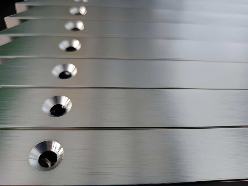
Real World Applications: Aluminium-based Deep Cavity Machining
Following the considerations discussed above, we will now explore practical solutions to deep cavity machining by using a real-life project as an example. An aluminium part with a very deep and narrow cavity was the primary subject of this project. Its measurements were as follows:
- Depth: 113 mm
- Width: 14.5 mm (at least)
- Corner fillet radius: 6 mm
Characteristic Features of the Aluminium Component:
- Material: Aluminium 7075-T6
- Part Measurements: 175.2 mm × 103 mm × 122.65 mm
- Internal Cavity Measurements: 146.2 × 83 mm
- Internal Cavity Corner fillet radius: 6 mm
- Narrowest Cross-Section Measurements: 14.5 × 14 mm
- Depth to radius ratio: 19:1
Due to the above-specified depth-to-radius ratio, this internal cavity can be referred to as an ultra-deep cavity.
Challenges and Limitations:
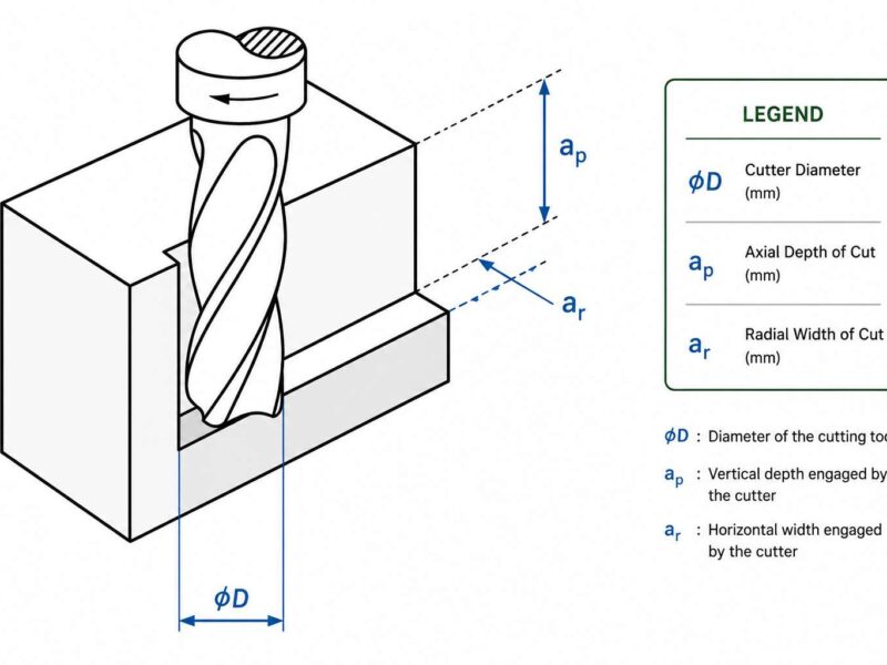
- A cutting tool with a diameter of 12 mm requires an overhang of at least 115 mm. Since the length of the tool must be more than 5 times its diameter, it causes poor rigidity. As a result, it can lead to wear and tear of the tool parts.
- During the process, aluminium chips are produced. However, their production rate is drastically greater than the removal rate. Due to this, they tend to wrap around the tools. The result is reduced efficiency and low performance.
- The walls of the internal cavity must have a surface roughness less than 0.8 micrometers. (Ra ≤ 0.8 micrometers)
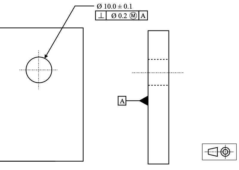
- The internal cavity must be perpendicular very precisely. It can only deviate by 0.1 mm.
Optimizing The Process
To deal with all challenges, we employed a set of strategies discussed below. This helped us achieve longer tool life, chip evacuation, and the required surface roughness.
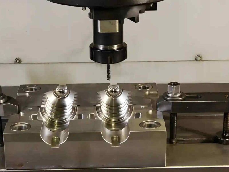
1. Finding a better way to enter the tool:
Before you begin the roughing process, pre-drill the starter or pilot holes. This will help you evacuate aluminium chips quickly. Additionally, it will also reduce the load borne by the workpiece during cutting.
We first drilled two holes at the bottom of the cavity. Each had a diameter of 22 mm. They served two primary purposes: first, they allowed the aluminium chips to exit the cavity. Second, they let the roughing tools enter the cavity. Graphically, these tools entered the cavity vertically through the Z axis, and then carried out the machining operations in the X-Y plane.
This strategy allows you to reduce the sudden impact force generated when the tools enter the cavity through the Z-axis.
2. Dividing the Entire Process into Three Stages:
We divided the roughing process into dynamic roughing, deep roughing, and corner refinement.
- Dynamic Roughing:
For this initial stage, we used a solid carbide end mill that had three wavy flutes. It had a diameter of 18 mm and a length of 100 mm. With a cutting depth from 0-65 mm, it could project up to 70 mm. To increase the efficiency of this stage, we operated at a spindle speed of 4000 rev/min, a feed rate of 1800 mm/min, and a cutting width of 1.8mm.
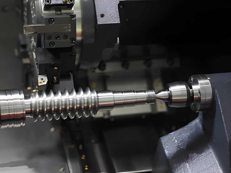
- Deep Roughing:
For the second stage, an insert cutter was used. Written below are some of the features:
- Diameter: 20 mm
- Vibration features
- Length: 200 mm
- Overhang: 120 mm
- Machining depth: 65 mm – 113 mm
We used stepwise roughing for better safety and efficiency. Its features are as follows:
- Spindle speed: 2800 rev/min
- Feed rate: 2000 mm/min
- Cut depth: 0.5 mm
- Cutting width: 14 mm
This allowed us to remove any extra material and attain finer, cleaner cavities.
- Corner Refinement:
In this final stage, we used a solid tungsten carbide end mill. It has the following features:
- Diameter: 12 mm
- Length: 200 mm
- Overhang: 125 mm
- Machining depth: 0 mm – 113 mm
The process used was secondary roughing. Its features are as follows:
- Spindle speed: 3000 rev/min
- Feed rate: 1500 mm/min
- Depth cut: 0.35 mm
It allowed us to remove any material leftover after the larger cuts in the previous step. All walls now had a surface finishing of roughly 0.2 mm.
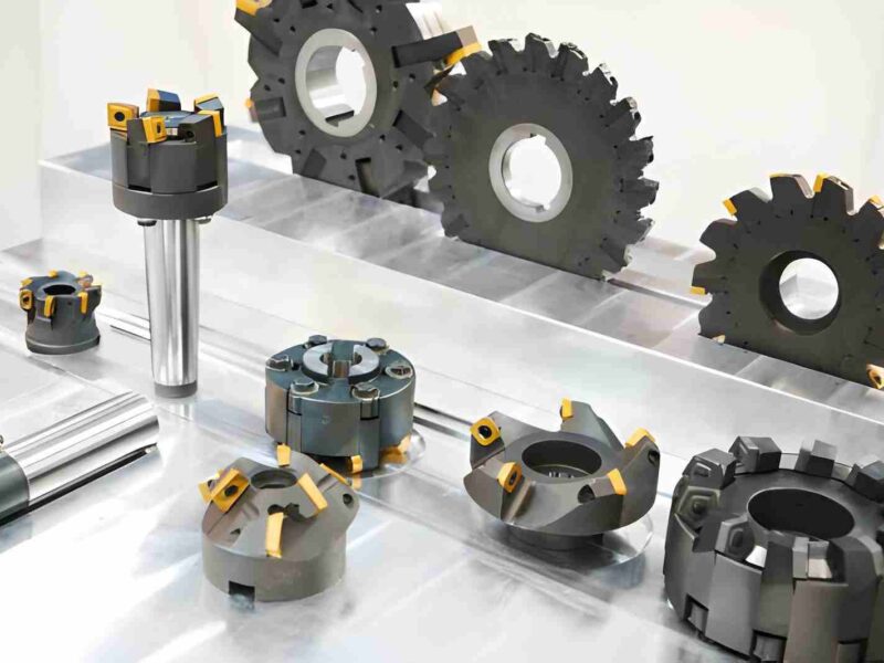
3. Choosing Suitable Materials and Designs
To achieve the desired results from deep cavity machining, it is essential to choose the right tools. However, it is equally important to have a skilled machinist who knows how to operate them correctly.
In our case, we chose YW-type carbide inserts. They proved to be more efficient than YT-type and YG-type inserts. Particularly, this was true in terms of heat dissipation and resistance to adhesion.
Optimizing The Finishing Tool Paths
In our project, we made use of two major types of finishing tool paths: one-pass spiral machining and layer-by-layer finishing.
-
One-pass Spiral Machining
Also known as the optimized tool path, one-pass spiral machining is based on a continuous cutting technique. Meaning, it only enters and exits the workpiece once throughout the entire process. The tool follows a downward spiral from the entry point to the exit point of the cavity.
Although some tool deformation and deflection are unavoidable, the spiral path helps reduce load on the tip by maintaining a uniform cutting speed. In addition to this, it also allows the internal cavity to maintain the required perpendicularity with minimum deflection.
-
Layer-by-layer Finishing
This technique is based on a ‘one at a time’ strategy. Essentially, it completes one horizontal layer at a time and then moves to the next. After every layer, the roughing tool re-enters the workpiece at a slightly deeper level by utilizing the auxiliary entry and exit points.
While layer-by-layer finishing is way more efficient than other available techniques, it ends up leaving visible marks on the workpiece where it enters and exits. The large tool overhang often results in uneven tool deflection. So as the tool rotates, it creates a slightly conical shape.
Contrary to the one-pass spiral machining, this method of deep cavity machining does not help the internal cavity maintain its required perpendicularity.
Using a Dual-Channel High-Pressure Coolant System
Pre-drilled holes are usually employed to help with chip removal. However, it is not enough to counter their high production rate. Therefore, continuous coolant flow is necessary to ensure aluminium chips are removed quickly. Ultimately, this will reduce wear on the tools and help them last longer.
In our project, we used a dual-channel high-pressure coolant system to ensure the timely removal of aluminium chips from the workpiece. This system is designed to deliver coolant from both vertical and horizontal outlets.
Final Results
By using efficient and high-performing equipment, at Premium Parts, we were able to ensure optimised results. Here are the outcomes we achieved:
We achieved a 42% reduction in the cycle time required for each workpiece. By employing the dual-channel high-pressure coolant system, we were able to increase the lifespan of our roughing tools by 125%. Moreover, we were also able to fulfill the requirement for surface roughness. Our overall surface roughness was less than 0.8 micrometers. Lastly, what gave us the most confidence in our workforce and equipment was achieving the desired perpendicularity with a deflection of less than 0.1 mm.
This project helped us understand that selecting the right tools alone isn’t enough to achieve accurate results. Having an optimised tool strategy is equally significant. Further, after looking at our results, we cannot stress enough the importance of testing different roughing techniques. This allows you to find a method that is best suited for your project.
In our case, segmented roughing techniques worked best. Lastly, in this scenario, the one-pass spiraling technique turned out to be better than the layer-by-layer technique in ensuring consistent results and minimum tool deflection.
Summary
This project was centered around discovering and finding solutions to common challenges associated with deep cavity machining. We were able to find practical solutions to chip removal, tool deflection, and issues pertaining to surface quality.
While the primary goal of this article was to answer any questions you may have, please feel free to reach out to us if you need help with something particular. At Premium Parts, we have a team of professionals ready to help you 24/7.
FAQs
Q1. What is CNC for Deep Profiles?
CNC for deep profiles refers to the use of CNC machines to perform deep cavity machining. Computer-controlled machines help us remove excess material in narrow and deep areas.
Q2. How to machine deep thin slots without damaging my tools?
First, remember to use the right tools. If your project matches ours, then use one-pass spiral machining. Most importantly, do not forget to use coolants to help with chip removal.
Q3. What is a practical application of deep hole CNC machining?
It is used in all industries. For example, during woodwork, machinists have to create deep holes for attachments to hold different parts together.