DESIGN GUIDELINES FOR INJECTION MOLDING
Injection moldingis one of the most crucial manufacturing technologies around us. Injection molding is so central in everything we do that more than half of the world’s plastic parts are made through this method. As a product designer and process engineer, it is essential to have a firm grasp of the design considerations for creating the perfect part. Getting your injection molding design right from the start could lower your part cost, improve functionality, shorten leadtimes, improve quality, and hasten part assembly. Getting your design wrong could result in the loss of thousands of dollars, brand reputation, customer dissatisfaction, and project failure.
At Premium Parts, our engineers and experts have put together the essential guidelines to help you create functional and intuitive parts. Continue reading for all our best tips!
• Tolerances
Tolerances are acceptable deviations from the specified dimensions of a part. In injection molding, the typical part tolerance is +/- 0.010 inches. Depending on the design, material, and budget, tolerances of 0.05 inches and even 0.002 inches are achievable. The tighter the tolerances, the higher the cost of the part.

• Walls
The thinner the walls, the easier the injection molding process. This is because thinner walls can cool faster, use up less material in their production, and cost less. Walls are critical structures in any injection molding design. Ensure that they remain uniform across the design to eliminate warping and reduce mold-in stress. Uniform wall thickness also allows for even flow of the molten resin during injection and guarantees that the mold is filled. If walls cannot be kept uniform, the thickness changes must be introduced gradually using a fillet or chamfer.

Walls that are too thick will sink, warp, and have internal pockets. The recommended wall thickness varies from material to material. Below is a summary of recommended wall thickness from resin to resin:
Resin material Recommended wall thickness
| Resin material | Recommended wall thickness |
| ABS | 0.045 to 0.140” |
| Acetal | 0.030 to 0.120” |
| Acrylic | 0.025 to 0.150” |
| PC | 0.040 to 0.150” |
| PS | 0.035 to 0.150” |
| PP | 0.025 to 0.150” |
| Nylon | 0.030 to 0.0115” |
| Liquid crystal polymer | 0.030 to 0.120” |
| Polyester | 0.025 to 0.125” |
| Polyethylene | 0.030 to 0.200” |
| PU | 0.080 to 0.750” |

On average, an injection molded part should have wall thicknesses within the ranges of 0.08 inches to 0.16 inches, while 0.02 inches is feasible.
• Ribs
Ribs are used when you want to add more stiffness even after your parts have been made to their recommended wall thicknesses. Ribs can also support horizontal sections without increasing their thicknesses. They help to eliminate cosmetic issues like voids, warps, and sinks. As a guideline:
i. Keep your rib thickness at 50% of the main wall thickness, as exceeding this level can result in sink marks.
ii. The height of your ribs must be less than 3 times the rib thickness.
iii. Use between 0.5 to 1.0 degrees of draft angle to ease ejection.
iv. The smallest distance between a rib and a wall must be 4 times the rib thickness.
v. Add a base fillet with a radius larger than 25% of the rib thickness.
vi. Keep the distance between ribs at least 2 times the nominal wall thickness.

• Bosses
Bosses are features in injection molded parts that serve as points of attachment or fastening. They are cylindrical projections that receive screws, threaded inserts, and other fastening hardware. They also facilitate mating parts. As a guideline, ensure that:
i. The section of your boss is not too thick that it causes sinks and voids.
ii. Your bosses do not merge into main walls and are supported with ribs connecting to adjacent walls.
iii. Bosses should have no more than 0.6 times the thickness of the main walls.
iv. Your boss’s base radius must be at least 0.25 times and no more than 0.5 times the main wall thickness.
v. For bosses with inserts, their outer diameters are 2 times the size of the insert.
vi. Keep the height of your boss at less than 3 times the outer diameter.
vii. Boss outer diameter should be two times the internal diameter.
viii. The draft angle of a boss outer diameter is at least 0.5 degrees, while that of the internal diameter is at least 0.25 degrees.
ix. The minimum distance between bosses is 2 times the nominal wall thickness.
x. The internal diameter of a boss to be used with a fastener is 0.8 times the nominal screw diameter.

• Living Hinges
Living hinges are used to connect two segments of a part. It comes with a flex or flip mechanism that allows for the opening and closing of the part. Living hinges are popular in plastic bottles, earphone cases, and other features with repeated open and close functions. When properly designed, your living hinge should last up to 1 million cycles without failing.
The best materials are P.P., PE, and Nylon for their flexibility and engineering suitability. As a rule of thumb, ensure:
i. Your living hinge is at least 0.20 mm thick and no more than 0.35mm in thickness. Thicknesses higher than this may cause the part to be stiff.
ii. If your living hinges span more than 150mm, divide it into two or more hinges to ensure a longer lifespan.
• Sharp Corners / Radii
Sharp corners generally result in stress concentrations and weaken injection-molded parts. When designing your parts, ensure that you round both internal and external corners. As a rule of thumb, ensure that:
i. Use an internal radius (fillet) that is at least 50% of the wall thickness.
ii. The external radius (fillet) is at least 150% of the wall thickness.
iii. Mathematically, external radius = wall thickness + internal radius.

")
Where R = External radius, r = internal radius and t = thickness
• Thick Sections
Core out thick sections in your part to prevent defects like warping and sinking. Coring is also vital to ensure that shrinkage is uniform in your parts. There must be a limit to the overall thickness of features on your part. You can hollow thick sections and use ribs to support them and increase stiffness.


• Gussets
Gussets may be considered as a subset of ribs. They also provide support and stiffness around structures in injection molded parts. The guidelines for ribs (covered above) also apply to gussets. Keep the following in mind when designing gussets:
i. The thickness of the gusset where it intersects with a nominal wall should be half the nominal wall thickness.
ii. The length of your gusset can range from 0.3 to 1 times the height of the gusset.
iii. Gussets can be up to 95 percent the height of the boss to which it is attached.
iv. The space between gussets must be at least two times the nominal wall thickness.
v. The recommended height for gussets is no more than 2 times the nominal wall thickness, while any height less than 4 times the nominal wall thickness is feasible.

• Textured surfaces
Textured surfaces must be around 0.060 inches from any parting line in the mold, although 0.040 from a parting line is feasible.
• Draft Angles
Draft angles are essential for facilitating smooth ejection of parts from the mold. All verticals must have draft angles to prevent cosmetic issues like drag marks. The following guidelines are recommended for draft angles in injection molding:
i. Keep draft angles at a minimum of 2 degrees. If you have tall features in your design, you can enlarge the draft angles to up to 5 degrees.
ii. Increase the draft angles by 1 degree per 25mm height for features taller than 50mm
iii. Increase draft angles by up to 2 degrees for injection molded parts that have textured finishes to prevent scratches and drag marks.

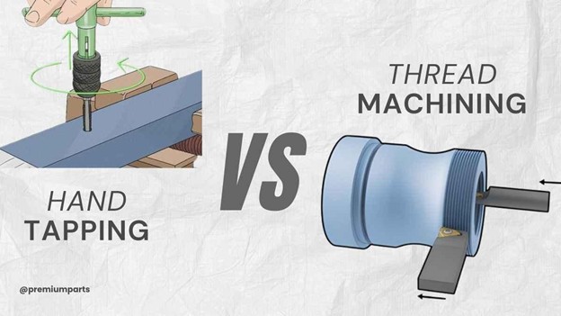
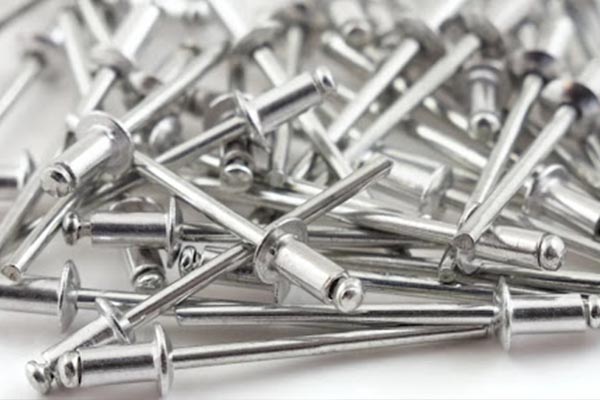
• Threads
Injection-molded parts can be designed to accommodate metal threaded inserts that serve as a hole for machine screws and other fasteners. Inserts are preferred to adhesives as they allow for applications where there might be a lot of coupling and disassembly. Please adhere to our guidelines on bosses to ensure that your bosses are well suited to receive threaded inserts. For threads, the following rules will help you achieve the best results:
i. Design threads to be buttressed or trapezoidal.
ii. Do not add threads directly on your part; use bosses.
iii. Allow your boss’s external diameter to be two times the nominal diameter of the insert or screw.
iv. Use a 0.8mm relief at the edges of the thread.

• Text and Lettering
Text, number, and lettering play essential roles in branding, information, instructions, and aesthetics. If your parts will contain any text and letterings, use the following guidelines for injection molding:
i. Ensure that texts are embossed (0.5mm height) and not engraved. I.e., raise your text above the part. Do not cut text into the part.
ii. Use Sans Serif fonts with bold, rounded font style and uniform thickness.
iii. The font size should be 20 points or larger.
iv. Ensure that the font is at least 0.020 inches in thickness
v. Align text perpendicularly to the parting line

• Gates and Vents
Locate gates at points where the plastic polymer intrudes against walls. Also, ensure that the gates in your design are small enough to separate the runner from the part and big enough to avoid any interruption of material flow during molding operations.
Vents are required for air release and heat exchange during molding. Ensure that vents are situated along the mold parting line, especially at locations that are filled last.