Since flat surfaces are easy to process, almost anyone can mill a pocket or face a block. However, the real struggle of a CNC setup shows up the moment a part needs a curve. Any smooth blend, any sweeping profile, or simply a shape that doesn’t sit neatly on one axis quickly becomes very complicated. This is where contour milling comes in, and it’s where a lot of programs either run clean or fall apart on the first pass.
Introduction to Contour Milling
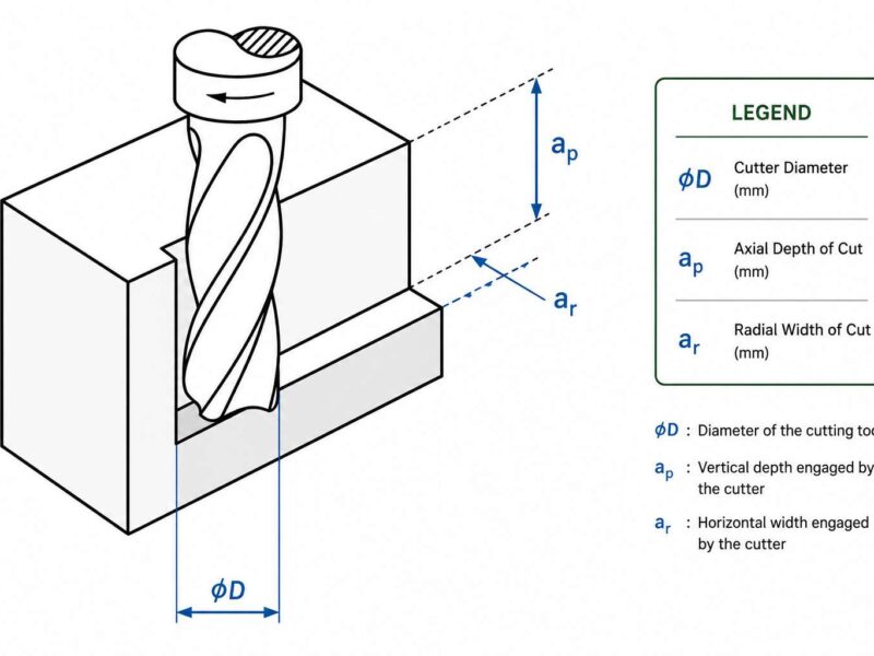
Contour milling cuts the outer shape or profile of a part by following a curved or irregular path instead of simple, straight lines. The cutter moves along the X, Y, and often Z-axis at the same time, tracing the actual contour rather than moving in a fixed or predictable pattern like basic facing and pocketing.
It is used wherever a part isn’t flat or square. As in, if it has curved edges, sculpted surfaces, blended fillets, or simply some free-form profile. It ranges from 2.5-axis work (a curve cut at constant depth) up to full 5-axis work, where the tool tilts and rotates to stay aligned with a complex 3D surface throughout the cut.
Types of Contour Milling Operations
- 2D contour milling: it cuts a profile at a constant Z depth. The tool moves around the X-axis and Y-axis while staying at one fixed height. It easily covers most outer edge profiling and some simple curved cutouts.
- 2.5-axis contour milling: it adds depth changes between passes, but each pass itself stays flat. Therefore, it is very common in stepped profiles or contours that are repeated at multiple depths.
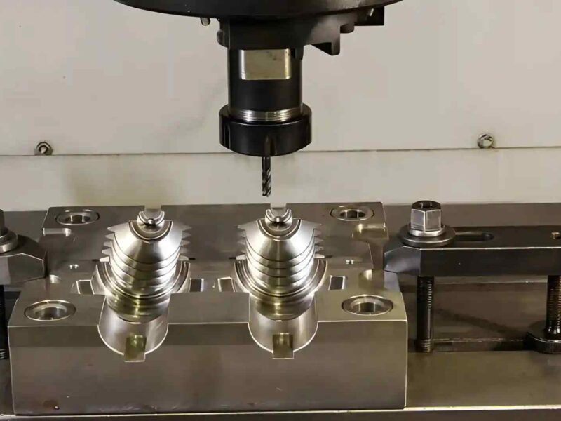
- 3D contour milling: it moves X, Y, and Z axes together to follow a sculpted surface. So, it is used for molds, dies and some parts having compound curves.
- 5-axis contour milling: it tends to add tool tilt and rotation while keeping the cutter angled correctly against the surface. This helps avoid the gouging and poor finish that happens when a 3-axis tool tries to reach steep walls or undercuts.
- Pocket contouring: it follows the inside wall of a cavity rather than an outer edge.
CNC Paths That Drive Contour Milling
- Profile milling: it follows the part’s boundary directly, usually in a single pass or steps up to the final size. It has predictable results; therefore, it is the default for most 2D contours.
- Parallel milling: it runs the tool back and forth in straight lines while stepping over between the passes. This works well on shallow 3D surfaces but tends to leave visible stepover lines on steep walls.
- Spiral milling: it moves in a continuous spiral instead of moving back and forth. This keeps engagement consistent, resulting in steadier cutting forces and fewer direction changes, which may lead to chatter.
- Z-level milling/waterline milling: it cuts horizontal slices at a fixed depth, then increments to another depth, and repeats the same. It is particularly common in mold work with steep walls.
- Pencil milling: it is a cleanup pass that picks up leftover material in tight corners and fillets that a larger tool can not generally reach.
Generally, most of the real programs combine two or three of these to get a good final result. For example, a roughing strategy may be used to clear bulk material and then a finishing strategy to match the surface.
Picking the Right Tool for Contour Cuts
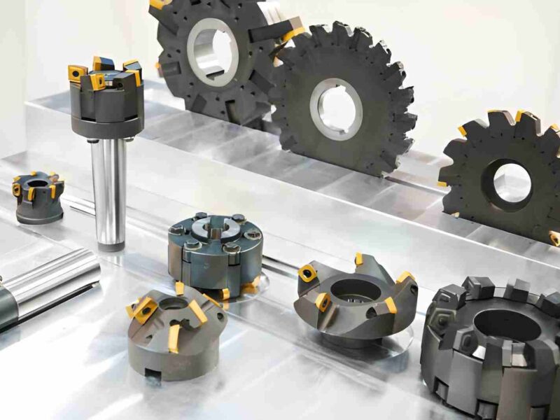
Ball Nose End Mills
They are the standard for 3D contours and sculpted surfaces. They have a rounded tip, which maintains contact across curved geometry without gouging. However, it then tends to leave scallops between passes and need a tight stepover to control them.
Bull Nose End Mills
They have a flat bottom with a small corner radius. They split the difference, having better surface contact than a ball nose on flatter areas, while still being able to handle light curves.
Square End Mills
They work well for 2D contours having vertical walls and very sharp corners. However, they tend to struggle with 3D surfaces because their flat bottom cannot follow a curve without leaving behind steps.
Tapered End Mills
They normally suit either steep wall 3D contours or deep cavities where a straight tool would not work well due to excessive deflection. The taper also adds rigidity as the reach progressively increases.
Flute count and Coating
More flutes generally give a better finish; however, at the cost of chip clearance. So, deep contour cuts in gummy materials usually use fewer flutes than a quick finishing pass in steel.
Working on a part with steep walls or compound curves? Send your drawing to Premium Parts and our team can confirm the tools and toolpath strategy before the job actually begins.
Setting Speeds and Feeds for Contour Work
Contour milling puts the cutter through constantly changing engagement. As in, the chip load shifts every time the path curves or steps down, so the parameters that work on a straight cut would most definitely cause problems the moment the tool turns at a corner.
Feed rate:
It usually needs to slow on tight curves and corners where the same programmed feed starts producing a higher actual chip load. Many controllers handle this through automatic corner feed reduction.
Stepover:
Stepover directly controls the surface finish on 3D contours. Tighter stepover means smaller scallops but more cycle time. The right value depends on tool diameter, required finish, and whether a finishing pass follows through.
Common Challenges in Contour Milling
Scalloping:
It is the wave-like texture left between passes on a 3D contour. Generally, it is caused by stepover spacing relative to tool diameter. To avoid it, tighter stepovers can be used; however, they will add to the cycle time.
Tool deflection:
It usually happens on steep walls because the contour paths often need greater tool reach to access angled or recessed geometry. The longer the reach, the more the tool bends under cutting force, consequently leading to dimensional errors.
Gouging:
It occurs on the undercuts when a 3-axis setup tries to cut geometry that actually needs tool tilt. The cutter cannot reach the area. Even if it does, it ends up wrongly removing material from the workpiece. This is the main reason complex contours move to 5-axis machining.
Chatter:
It especially shows up on curved paths when, during the tool’s direction change, the cutting force starts to vary. However, it can be avoided by using smoother toolpath strategies and steadier stepovers.
Heat buildup:
It shows up in cleanup passes mainly because small-diameter tools working in tight corners have a limited chip clearance. This is because they concentrate heat in a small contact area even when operating on lighter loads.
Practical Applications of Contour Milling
Contour milling shows up anywhere a part’s function depends on its shape instead of its dimensions.
- The mold and die work rely on it because the cavity and core surfaces are almost entirely contoured.
- Aerospace components with aerodynamic profiles, turbine blades, and structural fillets all depend on accurate contour cuts.
- Automotive panels, dies, and fixtures use it to produce the curved surfaces to stamp the sheet metal against.
- Medical implants and prosthetics, which need to match anatomical curves precisely, are almost entirely contour-machined.
- Some consumer products with an ergonomic grip or sculpted housing rely on contour milling.
Conclusion
Contour milling isn’t a single technique; rather, it is a set of decisions that have to be made one after another. First, decide the right toolpath strategy for the surface, then a tool that matches the geometry, and finally, the cutting parameters to account for the constant change. Our engineering team at Premium Parts reviews contour geometry, tooling, and cutting strategy together before a job starts cutting, so your batch comes back without any surface defects.
Talk to a Premium Parts engineer about your next contour milling project before the program gets locked in, and let us help you get the best results.
FAQs
How is contour milling different from pocket milling?
Contour milling follows the outer or inner boundary of a shape, but pocket milling clears material from inside a defined cavity, usually in a repeating pattern that fills the area rather than just tracing its edge.
Why does my part have visible lines on a curved surface?
It happens due to scalloping, which is caused by stepover spacing that may be too wide for the tool diameter and required finish. A secondary finishing pass with a smaller stepover usually fixes it even if the first pass leaves visible marks.
Do I need 5-axis machining for contour work?
Not necessarily. Many contours such as gentle curves, shallow 3D surfaces, and open profiles tend to cut fine on 3-axis equipment. A 5-axis usually is necessary when the geometry includes undercuts, steep walls, or areas a vertical tool simply can’t reach.
What tool should I start with for a new contour job?
Ball nose end mills are the safest starting point for 3D contours since they can easily handle curves without gouging. For flatter contours with some curvature, a bull nose tool often gives a better finish-to-cycle-time balance. Square end mills only work where the contour is essentially 2D with vertical walls.
Reach out to us, and our engineering team at Premium Parts will help you make a decision.
Why is my tool deflecting on deep contour cuts?
It usually happens due to reach. Contour paths normally need a tool to be able to extend beyond a standard vertical operation. This extra stickout reduces rigidity significantly. This can be fixed by switching to a shorter/tapered tool or by reducing depth of cut.