Thread specification is crucial for every mechanical assembly that uses a fastener. Whether it’s a turbine casing in aerospace or a garden hose fitting, everything counts on threads. And while the correct value has an enormous impact on thread performance, selecting the wrong type of threaded fastener is often done by purchasing the nearest metric bolt from inventory. It may work well at first, but then it doesn’t. Thus, you need to specify them properly. Understanding general types of threads and their geometric parameters is vital to the success of engineers and machinists. By doing so, we give them the technical basis to select the appropriate fastener the first time.
This guide illustrates thread basics and provides the essential geometric parameters that characterize thread performance. Besides, it also defines each applicable thread and the logic that experienced engineers apply in the field.
What Is a Screw Thread?
A screw thread refers to a continuous helical ridge, or helix, on the outside of a cylinder (external thread) or inside of an opening (internal). The helix converts rotational torque into linear axial force. These threads form the basis of every fastening device, leadscrew, and/or pipe fitting in engineering today. Two basic geometrical types of threads are present between the various thread families:
- Threads with a straight (parallel) profile from end to end. They maintain the same diameter along their entire length, and their primary use is for fastening or load-bearing purposes.
- Tapered Threads get smaller in diameter along the thread axis. They create an interference fit as the joint tightens. As a result, tapered threads are the standard choice for sealing fluids or gases.
Additionally, threads may be classified by their hand. The majority of threads are right-handed and tighten in a clockwise direction. However, left-handed threads are necessary in instances where the application of rotational torque would result in backing out or loosening of the fastener.
Geometric Parameters of Threads and Their Significance
Thread types are closely linked to their geometric characteristics. Each performance feature, clamp load, stripping force, coefficient of friction, and sealing ability, relates to the thread’s geometry. Here are eight key parameters engineers need to understand.
1. Major Diameter (Outside Diameter)
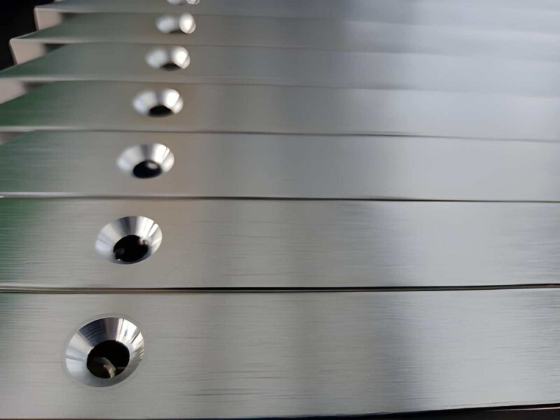
The major diameter is the largest diameter of a screw thread. Their measuring is usually from crest to crest on the outside of the screw or root to root on the inside of the screw. The major diameter basically designates the nominal size of a bolt. For example, an M10 bolt has a major diameter of 10 mm, whereas a 1/2″-13 UNC bolt has a 0.500″ major diameter. Engineers measure external major diameter with a plain micrometer. However, the internal major diameter requires a bore gauge or thread plug gauge.
2. Minor Diameter (Root Diameter)
A minor diameter is the smallest diameter of a thread form, and it is measured at the base of the thread form. In the case of an external thread (bolt), the minor diameter determines the tensile stress area of the bolt; this is the cross-section of the bolt that is most resistant to fracture in tension. Tensile stress area is calculated based on the minor diameter and pitch diameter, as stated in ISO 898-1. However, many people mistakenly believe that the major diameter has an influence on tensile stress.
3. Pitch Diameter (Effective Diameter)
The Pitch Diameter is the diameter of an imaginary cylinder that extends along the axial axis of the thread at the intersection of the flank of the thread at the location where there is equal width to the nominal pitch on the flanks of the thread. The pitch diameter is the most important geometric parameter for determining the fit class of a threaded fastener and its ability to interchange with other fasteners. Thread gauging with Go/No-Go gauges fundamentally checks pitch diameter conformance.
4. Pitch (P)
Thread pitch is the distance between similar points on adjacent crests of a thread measured parallel to its axis of rotation. The unit of measure for pitch in metric threads is millimetres (e.g., M10 x 1.5 has a pitch of 1.5 millimetres). However, in inch-based threads, the pitch is defined as the number of threads per inch (TPI), which has the reciprocal relationship as the pitch: pitch = 1/TPI.
Table 1: Pitch vs. TPI Reference (Common Sizes)
| Metric Thread | Pitch (mm) | Inch Thread | TPI |
| M6 | 1.0 | 1/4″-20 UNC | 20 |
| M8 | 1.25 | 3/8″-16 UNC | 16 |
| M10 | 1.5 | 1/2″-13 UNC | 13 |
| M12 | 1.75 | 5/8″-11 UNC | 11 |
| M16 | 2.0 | 3/4″-10 UNC | 10 |
5. Lead
The lead of a nut or threaded fastener refers to the distance an item can move forward with one complete rotation of the nut (360°). The lead for a single-start thread equals the pitch. For multi-start threads, the lead will equal the pitch multiplied by the number of starts. For example, a double-start thread (such as an M10×1.5) will have a lead of 3.0 mm; thus, this double-start thread moves twice as quickly with each rotation and is often used in quick-release devices and ball-screw systems.
6. Thread (Flank) Angle
The angle formed by the two flanks (sides) of a thread in the axial (vertical) plane is referred to as the thread angle. This angle will determine how much friction is produced and how the force will be transmitted to the bolt and its load. Some of the most common standards used for the thread angle are as follows:
- 60°: ISO Metric, Unified (UNC/UNF), and UN Thread Families
- 55°: British Standard Whitworth (BSW) and BSP Pipe Threads
- 29°: Acme Threads
- 7°: Buttress (asymmetrical; ~45° or load flank and ~7° or clearance flank)
- 0° : Square (no flank angle, maximizes efficiency, most difficult to manufacture).
7. Helix Angle
The angle between the thread helix and a plane that is perpendicular to the axis of the thread is called the helix angle. This angle determines whether the thread can be self-locking.
For the thread to be self-locking when subjected to an axial load, the helix angle must be less than the friction angle, which is typically 4° or less for the case of steel-on-steel threads. Position retention of threaded connections is accomplished through the use of small helix angles when utilizing screws for this purpose. Ball screws with high leads use larger helix angles because they are more efficient than using smaller helix angles.
8. Thread Depth (Height)
The height or thread depth is half the radial distance between the major and minor diameters. The theoretical depth of metric threads can be calculated as H = (√3/2) × P, approximately H ≈ = 0.866P; however, to have adequate clearance at both crest (tip) & root (bottom) without losing the load-carrying surface area of threads, the actual engaged depth is usually 5H/8.
Types of Threads and Their Geometric Parameters: Major Thread Standards
Metric Threads (ISO 68-1 / DIN 13)
ISO metric screw threads are the worldwide standard type of screw threads for fastening purposes. The screw thread is made with a flank angle of 60° and rounded threads (Radius = H/6) on the roots of the screw and flat crests. The designation is formatted as M[diameter] x [pitch]. If the pitch is not included, the designator defaults to coarse pitch (for example, M12 defaults to M12 x 1.75).
Metric threads divide into coarse (MJ) and fine pitch series. The fine pitch type (M10 x 1.0 vs. typical M10 x 1.5) provides better resistance to coming loose from the effects of vibration and also has a greater tensile area. This makes it the preferred type for automotive powertrain uses. The ISO Tolerance system provides positional tolerance codes (e.g., 4H, 6H, 6g, etc.) defining the class of fit for each of the two mating thread pairs.
Table 2: ISO Metric Coarse Thread Key Parameters
| Size | Major Dia. (mm) | Pitch (mm) | Minor Dia. (mm) | Pitch Dia. (mm) | Stress Area (mm²) |
| M6 | 6.000 | 1.0 | 4.917 | 5.350 | 20.1 |
| M8 | 8.000 | 1.25 | 6.647 | 7.188 | 36.6 |
| M10 | 10.000 | 1.5 | 8.376 | 9.026 | 58.0 |
| M12 | 12.000 | 1.75 | 10.106 | 10.863 | 84.3 |
| M16 | 16.000 | 2.0 | 13.835 | 14.701 | 157 |
| M20 | 20.000 | 2.5 | 17.294 | 18.376 | 245 |
Unified Thread Standard (UNC / UNF / UNEF) – ASME B1.1
North America uses the Unified Thread System on all fasteners throughout North America, and it continues to be a common specification in defence and aerospace. The Unified thread system uses a 60° flank angle (as with the metric threads); however, the distances of the threads are all measured in inches.
The three major series of Unified thread fasteners are Unified National Coarse (UNC), Unified National Fine (UNF), and Unified National Extra Fine (UNEF). Tolerance classes 1A/1B through 3A/3B define fit tightness from loose assembly (Class 1) to precision close fit (Class 3). Because of the weight of fasteners, aerospace structures generally prefer UNF due to the potential for vibration and fatigue being greater for fine-pitch fasteners.
British Standard Pipe Threads (BSP) – ISO 228 / ISO 7
BSP threads have a 55° angle and can be found on almost every hydraulic and pneumatic connection manufactured outside of North America. There are currently two active versions of BSP threads:
- BSPP (British Standard Pipe Parallel, G-series): A straight thread that uses a face seal or O-ring in addition to a nominal bore size number to designate these threads as G 1/2
- BSPT (British Standard Pipe Tapered, R-series): 1:16 taper (3.576° half angle) produces a mechanical interference seal on assembly. The thread designation will be either R (for external threads) or Rc (for internal threads).
BSPT and NPT both appear similar, but are not interchangeable. The difference between the 55° flank angle on the BSP threads and the 60° flank angle on the NPT threads will cause the two to cross engage partially and may cause the two to jam or leak. It is, therefore, very important to know this difference when performing maintenance work on fluid power systems.
Table 3: BSP Thread Dimensional Reference
| BSP Size | OD (mm) | OD (inch) | TPI |
| 1/8″ | 9.73 | 0.383″ | 28 |
| 1/4″ | 13.16 | 0.518″ | 19 |
| 3/8″ | 16.66 | 0.656″ | 19 |
| 1/2″ | 20.99 | 0.825″ | 14 |
| 3/4″ | 26.44 | 1.041″ | 14 |
| 1″ | 33.25 | 1.309″ | 11 |
| 1-1/2″ | 47.80 | 1.882″ | 11 |
| 2″ | 59.61 | 2.347″ | 11 |
NPT / NPTF Threads (ASME B1.20.1)
NPT threads in North America are comparable to the BSPT taper ratio of 1:16, but they have a flank angle of 60 degrees. The major uses of NPT pipe threads are for water, gas, and hydraulic systems. NPTF pipe threads are dry-seal versions of NPT threads that can provide a pressure-tight metal-to-metal seal without the use of a sealant by utilizing controlled interference at both the flanks and the root of the thread. This is particularly important in aerospace fuel systems since sealant thread compounds are not allowed in these systems.
Square Threads
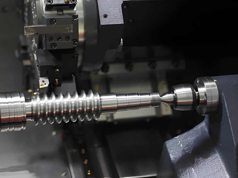
Square threads have zero flank angles, and the thread profile resembles a rectangle. They produce the lowest amount of axial friction of any thread form and therefore, provide the highest mechanical efficiency (up to 50% vs. Acme ~30%). However, the absence of an angled flank means that there is no radial component of the normal force acting on square threads. This leads to square threads being unable to self-center, tolerate wear, and be extremely difficult to manufacture with conventional tooling. You’ll find square threads on machine tool lead screws, vise spindles, and hydraulic jack screws where maximum power transmission efficiency is critical.
Acme Threads (ASME B1.5)
ACME threads are a modern development of square threads, as they have a 29° included flank angle that improves machinability dramatically over square threads. This allows the use of split-nut engagement on manual leadscrews. While the trapezoidal thread geometry is still very efficient, it continues to handle axial thrust loads in both directions and provides additional wear before the backlash is unacceptable. The metric equivalent of the trapezoidal thread in the ISO 2901 standard is the TR-series (30° angle).
Buttress Threads (ASME B1.9)
Buttress threads carry axial loads in one direction only. The load flank is virtually perpendicular to the axis (.7° or less), and the clearance flank is at a steep angle (approximately 45°). The asymmetry provides maximum load-bearing capacity to the working face with the least risk of being unable to manufacture the thread. Some examples of where Buttress Threads are found include in artillery breech rings, hydraulic cylinder end caps, large diameter pipe couplings in the oil & gas industry, and structural tie-rod anchors.
How to Confirm Types of Threads and Their Geometric Parameters in the Field?
One of the most frequent and expensive mistakes made by both maintenance and manufacturing personnel is failing to properly identify the standard of a threaded fastener. The correct method to accomplish this task includes the following steps:
- Step 1: Determine whether the thread is tapered; this can be done by using a thread pitch gauge or laying the threaded fastener next to a known parallel flat surface. It is important to note that tapered threads will display a concurrent change in diameter of approximately 25-30mm.
- Step 2: Measure the “major” diameter of the thread; use digital calipers for measurement of the major diameter of external threads and/or use a bore gauge set to measure the major diameter of internal threads; record both the metric and inch measurements.
- Step 3: Determine TPI or pitch of the thread, using a thread pitch gauge (also known as a leaf gauge set). Match the tooth profile of the thread to the appropriate TPI or pitch of the thread. Use measuring peaks along a prescribed distance to cross-check your TPI or pitch calculation.
- Step 4: Measure the flank angle to verify the thread type; if using a profile gauge with a 55° angle, you are most likely dealing with either BSW or BSP threads. If using a profile gauge with a 60° angle, you are probably dealing with either Metric or UN threads. The flank angle is also the most definitive method of distinguishing between NPT and BSPT taper thread standards if you are measuring tapered threads.
- Step 5: Cross-compare your measurements with the applicable standard’s tables; once you have determined the major diameter, TPI or pitch, and flank angle, reference the combination against the appropriate standards (ISO 261, ASME B1.1, ISO 228, ASME B1.20.1).
Selecting the Right Thread: Engineering Criteria
Thread selection in a real project involves balancing several competing requirements simultaneously. The table below summarises the key selection factors:
Table 4: Thread Type Selection Matrix
| Application | Priority | Recommended Thread | Key Geometric Feature |
| General fastening (global) | Interchangeability | ISO Metric (M-series) | 60° flank, rounded root |
| North American fastening | Standard compliance | UNC / UNF | 60° flank, inch TPI |
| Hydraulic pipe sealing (EU/Asia) | Leak-free seal | BSPT or BSPP + face seal | 55° flank, 1:16 taper |
| Hydraulic pipe sealing (USA) | Leak-free seal | NPT / NPTF | 60° flank, 1:16 taper |
| Power transmission (leadscrews) | Efficiency | Acme / Trapezoidal (Tr) | 29° flank, wide root |
| High-vibration environment | Anti-loosening | Fine-pitch metric (MF) | Small pitch, high TPI |
| Unidirectional thrust loads | Load capacity | Buttress thread | 7° load flank, 45° clearance |
Conclusion
Every engineer, machinist, and procurement person involved with mechanical assemblies is going to need a thorough understanding of the various kinds of threads that are available, as well as their geometric characteristics. The major diameter, pitch diameter, pitch, lead, flank angle, helix angle, and thread depth are measurable characteristics associated with every thread. Therefore, they are not ambiguous specifications, but rather the characteristics necessary to determine if a joint can carry its design load, keep a pressure-tight seal for many years, and can be produced with consistent quality by assembly.
At Premium Parts, we produce and supply precision components using all types of threaded standards from standard ISO metric to UNC/UNF, as well as custom-designed Acme and buttress threads. If you need assistance with thread specifications, tolerance selection, or the most suitable manufacturing processes, please contact our engineering team to discuss your needs.
Frequently Asked Questions
What are the geometric parameters of a thread?
There are eight primary parameters to define screw threads geometrically, which include major diameter, minor diameter, pitch diameter, pitch, lead, flank (thread) angle, helix angle, and thread depth. All of these parameters together completely define any and all aspects of screw thread geometry.
What is the difference between pitch and lead?
“Pitch” is defined as the axial distance between two adjacent thread crests, while “lead” is defined as the axial distance advanced due to one complete revolution of the screw. For a single start screw thread, the values of lead and pitch will be the same. For a double start screw thread, the value of lead is equal to two times the value for pitch.
How do I identify whether a thread is BSP or NPT?
The most accurate method for determining the type of pipeline thread is to use a thread pitch gauge and measure the flank angle; a “BSP” thread flange angle will be at 55° while a “NPT” thread flange angle will be at 60°; both will have the same 1:16 taper. You can use the appropriate pitch gauge to measure the flank angle to confirm if it is a “BSP” or “NPT” thread. Measurements of the major diameter can provide additional verification, but will not be definitive by themselves.