Counterbore vs. countersink holes can be used to refer to similar holes. Their design may appear the same on a CAD model. However, their use, geometry, and purpose vary in character.
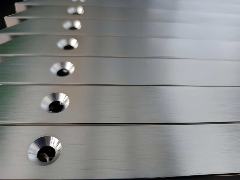
A counterbore is formed to seat bolt heads, and fasteners are flush or below the surface. It provides a recessed shape like a hemisphere with a flat bottom. In contrast, a countersink hole features a conical hole. It usually fits angled fastener heads, allowing it to meet the surface of the part smoothly.
The choices about each, particularly in high-tolerance CNC-machined parts, require an understanding of when and why the feature needs to be used. A wrong choice may result in assembly failure, improper alignment, and reduced load paths.
In this article, we’ll talk about the performance-based and design-sensitive distinction between counterbore and countersink holes, including geometry, functionality, tooling behavior, GD&T considerations, and manufacturing limitations of precision components.
Counterbore and Countersink: Functional Difference
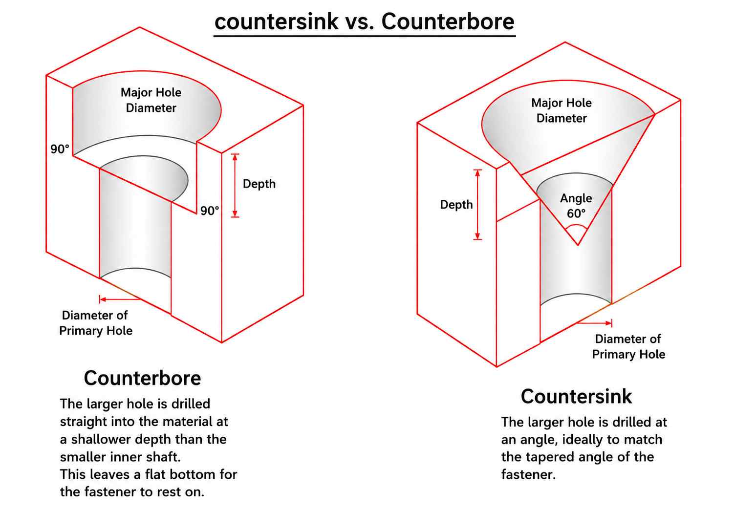
Counterbore vs countersink hole – Illustration (Reference: The Engineering Knowledge)
The counterbore hole provides a compressed, receptacle-like space at the base of the fastener head. It assures that it leaves the exterior surfaces clean, so that socket-head bolts or washers can be effectively seated in them, without protruding.
Conversely, a countersink hole is a cone-shaped hole that recesses the head of a screw to hide it under the surface. They are common in aero panels, electronic cases, and consumer goods.
The selection of a counterbore vs a countersink hole is based on the
- Type of load
- Space
- Type of assembly
Counterbores are usually more stable and have more contact surface in axially loaded joints or rotating systems.
Misconceptions Between Counterbore Vs Countersink in Design & Production
Countersinks and counterbores are often confused. These are interchangeable features for many board designers. These are responsible for creating component layouts, mounting holes, and fastening points in assemblies.
However, there is a misconception because CAD models often make countersinks and counterbores appear visually similar. This similarity leads to the false assumption that they serve the same function. Nevertheless, the wrong feature will result in bad CAM programming and wrong toolpaths. The outcome is inappropriate, machining, and expensive re-adjustment in the manufacturing process.
The other common error is to make use of spotfaces rather than using counterbores, where clearance of the fastener is needed. Spotfaces leave the surface only levelled, without much space for the fastener heads. It does not allow bolts to sit in place properly. Additionally, it impacts the functionality and part strength.
These design errors can lead to part failure, poor assembly fit, or rework. There are also misjudgment errors at this stage, which cost time and slow production schedules a lot.
At Premium Parts, our team helps you avoid making such errors during the early stage of the design. We provide comprehensive DFM advice, drawing reviews, and CADs. It is also in the clarification of the callouts that we ensure that the correct hole type has been specified.
The precision analysis results in proper toolpaths, a fit, and a sound mechanical outcome. With us, your parts come accurate, in a ready-to-assemble and production-ready form.
Counterbore vs Countersink: Callout Symbols
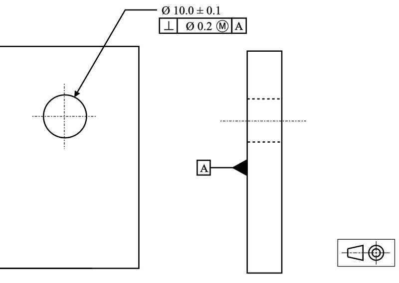
Engineering drawings require accurate callouts to prevent delays in production and machining mistakes. The differences between counterbore and countersink symbols enable engineers and machinists to read specifications accurately. These symbols are part of Geometric Dimensioning and Tolerancing (GD&T), used to ensure that the design intent created in CAD is accurately reflected in the final machined part.
Counterbore Hole Callout Interpretation
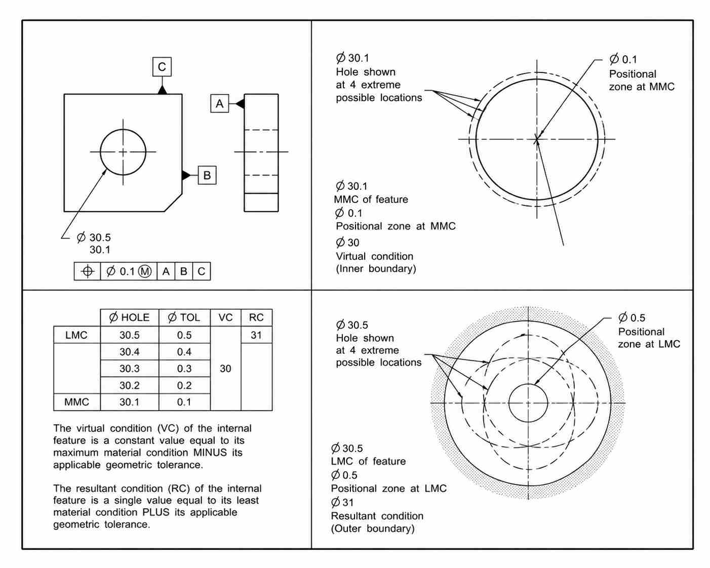 Positional tolerance for counterbore and clearance hole (Reference: Eng-Tips)
Engineering drawings must include appropriate callouts. It helps you avoid ambiguity in production. The counterbore symbol (⌴) denotes a cylindrical recess, while the countersink symbol (⌵) denotes a conical feature.
A sample counterbore hole callout looks like this: “Ø10 ⌴ Ø20 x 5”, meaning a 10mm hole with a 20mm diameter counterbore 5mm deep. Each figure must be in line with the fastener head dimensions.
Wrong symbols or missing depth values lead to scrap or defective assemblies. Our engineering team cross-verifies every drawing for symbol clarity and tolerance alignment.
Countersink Hole Callout Interpretation
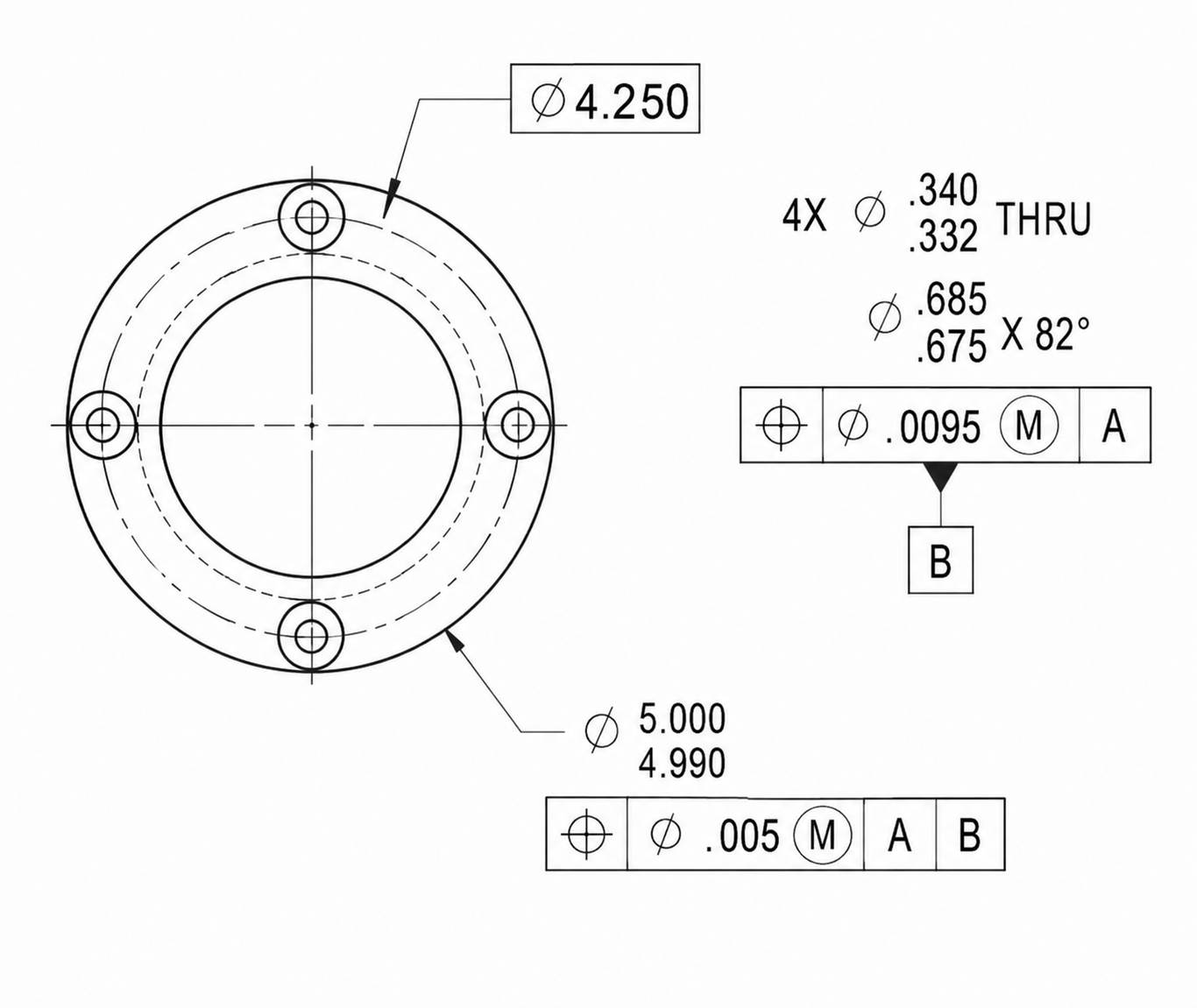 Countersink positional tolerance interpretation (Reference – Eng-Tips)
A typical countersink hole callout appears as: “Ø8 ⌵ 90°”, specifying an 8mm pilot hole with a 90-degree countersink.
The angle is critical for proper fastener seating. Deviations can cause poor fit and torque issues. For tight-tolerance parts, the depth of the conical recess must also be indicated to match fastener geometry.
Comparative Analysis: Counterbore Vs. Countersink
Understanding the differences between these two hole types is important in preventing assembly failure. The following aspects clarify how geometry and tooling affect their use.
Shape
A counterbore is a straight-sided, flat-bottomed recess acceptable to socket-head bolts. A countersink, instead, forms a tapered conical hole that fits that of a flat-head screw. The different shapes have different mechanical performances. So, they also require special machining processes.
The design without geometry considerations can lead to a fastener misfit, insufficient clamping force, and structural imbalance.
Tool
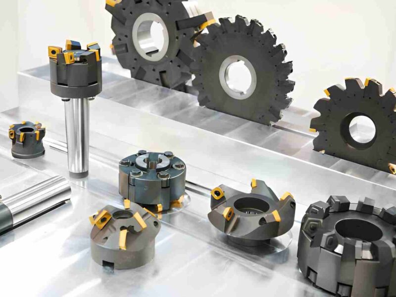
The counterbores have end mills and piloted counterbore tools of accurate depth and diameter. Countersinks need fluted conical cutters with particular point angles such as 82, 90, or 100 degrees. The precision and cycle time are influenced by the tool selection.
Working with the incorrect cutter undermines the integrity of the mating surface and causes an overcut feature. End mills or piloted cutters are employed in counterbores. The countersink requires fluted tools to be angled 82 ° to 100 °.
Depth Control
Flat-bottom counterbores allow direct depth setting with easier visual inspection. Countersinks are controlled by angle and engagement depth. This complicates their measurement. Poor depth control in either feature risks improper seating, bolt fatigue, and inadequate clamping force.
Engineers must verify hole geometry using appropriate metrology tools during inspection. Counterbores are easier to control due to flat-bottom geometry. Countersinks require angle and depth alignment.
Tolerance
Counterbore hole dimensions are easier to measure using depth gauges and standard calipers. Their common tolerances can vary between plus or minus 0.05 and 0.10 mm, depending on the intended part use. On the other hand, countersinks require angular and radial precision to match fastener cones. Misalignment in tolerance affects joint performance and aesthetics.
Premium Parts ensures dimensional accuracy through in-process inspections during machining.
- Validated CAM programs are used to control toolpaths for every critical hole feature.
- Counterbore hole dimensions are easier to inspect using calipers for diameter and depth.
- Countersink accuracy depends on angle measurement tools like optical comparators or digital protractors.
Surface Finish
Counterbores typically produce uniform mating surfaces due to consistent bottom surface machining. Countersinks require deburring and surface prep to ensure flush fastener contact. Improper finish leads to fastener loosening or cosmetic defects.
Our finishing workflows optimize hole edges to maintain performance and visual quality standards. Counterbores yield cleaner mating surfaces. Countersinks may demand deburring to ensure flush contact.
Countersink vs Counterbore: Pros of Each Hole Feature
Here is the list of benefits and drawbacks of countersink and counterbore. Let’s go through it:
Benefits of Counterbores
- Furnish more surface area of contact between torque-sensitive fasteners.
- Improves the rotating power and load assemblies of joints.
- Minimize bolt sticking out in assemblies that are stacked and dynamic.
- Permit a more convenient visual and dimensional examination.
- Hold up the clamping force when there is mechanical stress.
Benefits of Countersinks
- Facilitate flush finishes by using flat screw heads.
- Suitable for lightweight, cosmetic, and electronic assembly.
- Assist in the centring of fasteners and align them.
- Quick to machine, less production, and fewer tool changes.
- Need to have fewer materials removed to clear the path.
Design Considerations For Counterbore Vs. Countersink Holes
Counterbore or countersink holes are designed correctly to get proper fastener fitting and structural and manufacturing convenience.
Counterbore Hole Drilling
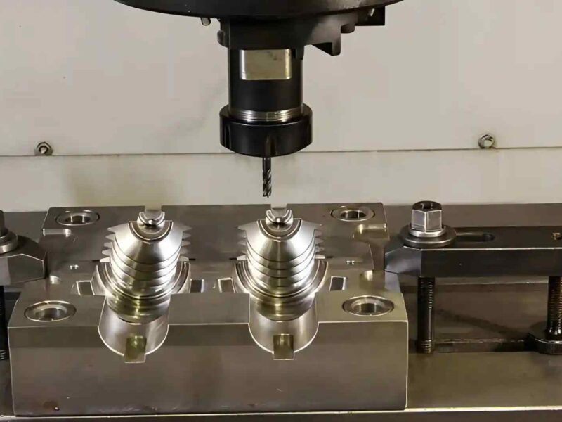
Use a twist drill to make a pilot hole of a depth sufficient for your purpose. After that, a counterbore cutter or end mill can be used to machine a flat-bottom recess.
It is recommended that the tool should possess identical diameters as well as heights as the fastener head and the shoulder, so that they rest suitably.
Countersink Hole
Start working with a drilled hole, then use a countersink bit that has the right degree of the included angle, which is 82, 90, or 100, depending on the counter. There should be no chatter, and even the bit should be concentric.
Fastener Compatibility
Counterbore holes apply to socket-head or hex bolts and are drilled in such a way that the fastener recesses below the surface. Countersinks make the flat-head screws fit against the parts.
Tool and Material Considerations
Rigid or hardened materials require the use of solid carbide and end-coated HSS tools. Maintenance of sharp corners helps to avoid tool wear and dimensional drift.
Design Error Prevention
Make sure to include GD&T symbols properly and find the hole geometry that suits the fastener Head, to prevent the misfit or load failure.
Material and Tooling Implications in CNC Machining
Here are the common influences of materials and tooling strategies on the machining of the counterbore and countersink holes:
Behavior in Various Materials
In soft materials like aluminum, countersinks cut cleanly. But in plastics and composites, it may cause chipping and cracking.
Counterbore holes in hardened steel require sharp carbide tools and optimized feeds. Thermal expansion must be managed to prevent tolerance drift. Our machining cells are calibrated by material class to validate that reliable cuts can be made even on exotic alloys and high-temp polymers.
Tool Selection and Wear Factors
- Countersinks demand consistent edge geometry to keep proper angles. Wear reduces seating quality.
- Counterbore tools must maintain edge flatness. Dull cutters cause uneven recessed floors, risking bolt misalignment.
Premium Parts monitors tool wear digitally. They ensure consistent outcomes during batch or high-volume production.
Design Mistakes That Affect Part Quality
Let’s identify general design errors such as symbol confusion and feature misuse, which cause part failures or expensive rework.
Misread Symbols and Wrong Hole Types
Missing or improper use of counterbore and countersink symbols in technical drawings leads to interpretation mistakes. This causes wrong toolpath creation, improper inspection arrangements, and higher scrap rates.
Overengineering or Under-Specifying the Feature
The counterbore specified where a spot face is adequate will result in follow-up machining operations and a higher cost of manufacture. An undefined countersink causes failures of torque and cosmetic defects.
We recommend our customers select the type of holes that is a trade-off between performance, speed of production, and cost.
Selection Criteria Between Counterbore Vs Countersink
The table highlighted critical aspects to help you make the right decision.
| Criteria | Counterbore | Countersink |
| Fastener Type | Socket-head bolts | Flat-head screws |
| Load Type | Axial, structural | Light shear, cosmetic |
| Appearance | Recessed surface | Flush with surface |
| Machining Time | Longer due to depth and tool changes | Faster due to simpler geometry. |
| Tolerancing Ease | High: easier to measure and inspect | Lower: angle + depth hard to match |
| Common Application | Machinery frames, structural joints | Paneling, electronics, enclosures |
We review your CAD models and advise on optimal feature selection during DFM consultation. This saves unnecessary revisions and saves time.
Final Thoughts
Choosing between a counterbore vs countersink hole may seem simple, but its impact is measurable. Assembly fit, stress performance, and inspection time, with hinges on proper feature use.
At Premium Parts, we deliver production-ready components where precision matters. From counterbore hole dimensions to tolerance-driven surface prep, we support your full product lifecycle.
Whether prototyping or scaling up, our engineers ensure your fasteners sit right and stay tight.
FAQs
Q1. What is a countersink hole, and how can it be used?
A countersink hole allows flat-head screws to be flush with the surface. It can be used on convenient assemblies and appearance panels, with restricted height clearances. It’s helpful for enclosures, housings, and aerospace components where external faces require a uniform finish.
Q2. What does a counterbore hole callout mean?
Counterbore hole callout means pilot hole diameter, counterbore diameter, and counterbore depth. It has the sign ⌴. An example is a 10mm hole with a 20 mm wide 5 mm deep counterbore designated 10mm 20 x 5. A counterbore hole specification comprises the main hole diameter and the counterbore diameter and depth, which is frequently shown as 10mm 20 x 5.
Q3. What is the difference between Spotface vs counterbore?
A Spotface is made only to flatten an area beside a hole without adding extra depth. A counterbore creates a cylindrical distance so as to provide a clearance for bolt heads. One may use Spotface when a counterbore must be added and end up with interference, bad seating, or mechanical instability of high-load joints.
Q4. Are counterbore vs countersink symbols commonly misread?
Yes, confusion between ⌴the (counterbore) symbol and the ⌵ (countersink) symbol causes tooling and production mistakes. Such symbols are critical to GD&T. A lack of callouts and improperly placed callouts can lead to a part being rejected, an inspection backlog, and rework in CNC programming.