Side milling is one of the most accurate and verifiable CNC peripheral operations in modern machining. Whether you are cutting a deep slot into a housing for a gearbox, cutting square shoulders on a structural bracket, or performing straddle milling on parallel faces of a forged part, side milling can provide you with dimensional tolerances and surface finish qualities that other operations cannot replicate.
Engineers extensively use side milling in many aerospace, automotive, energy, and medical manufacturing programs. This guide will explain how side milling functions, the cutters to use, and how side milling compares with other milling techniques. You’ll also learn when to select side milling as a manufacturing approach to consignment quality parts.
What Is Side Milling?
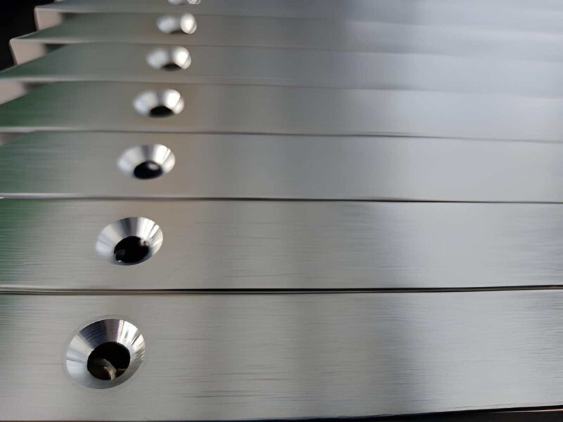
Side milling is a CNC milling operation that employs a cylindrical cutter that rotates, while it engages the workpiece along the edge of its cutting teeth on the outside diameter of the tool to cut material from the vertical side of the workpiece. The rotation of the cutter axis is parallel to the machined surface, and the depth of cut is determined radially. However, in contrast to face milling (where cutting occurs at the end of the cutter) and plain milling (where material is removed only from the top of the workpiece), side milling produces a cutting action on the side of the workpiece and is suitable for making vertical walls, open slots, steps, keyways, and precise, square shoulders.
Side milling runs on either vertical machining centers (VMC) or horizontal milling machines, depending on the geometry of the cutter and the design of the feature.
How Side Milling Works: The Mechanics Behind the Cut
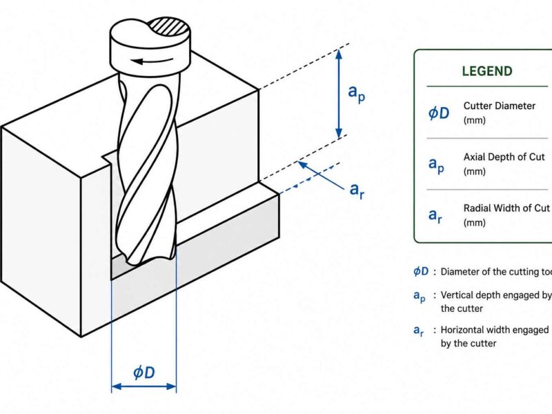
When the side milling cutter rotates, each of its outside teeth makes a shearing motion on the part. As the table feeds the part linearly, the thickness of the chip builds from zero at the beginning of each section. Subsequently, it increases to a maximum at the center of each section and then decreases back down to zero before it leaves. This reduction or increase of chip-load creates chatter if the parameters are incorrect. Important mechanical aspects of side milling include the following:
- The radial depth of cut (RDOC) controls how far the cutter engages radially into the workpiece. Keeping below 30% of the cutter diameter controls cutting forces and deflection.
- The axial depth of cut (ADOC) determines the height of the feature being cut, equal to the cutter face width for full-width slot cuts.
- Chip thickness varies cyclically as each cutting edge enters and exits the cut, which drives the selection of feed rate and spindle speed.
The workpiece surface that is being cut is perpendicular to the motion of the cutter. The teeth on the side of the cutter remove material as the workpiece moves. However, the shape of the cutter’s peripheral surfaces has a significant impact on the final surface finish and dimensional accuracy.
Climb milling (down milling) is good when you perform CNC side milling as the first choice. In this process, the chip starts thick and thins toward the exit, producing lower cutting temperatures and better surface finish on the machined surface. Conventional milling (up milling) is an option when the use of climb milling will create unsafe conditions due to either backlash in the machine or instability of the workpiece. And this rarely occurs on the newer CNC machine tools with a ball screw drive.
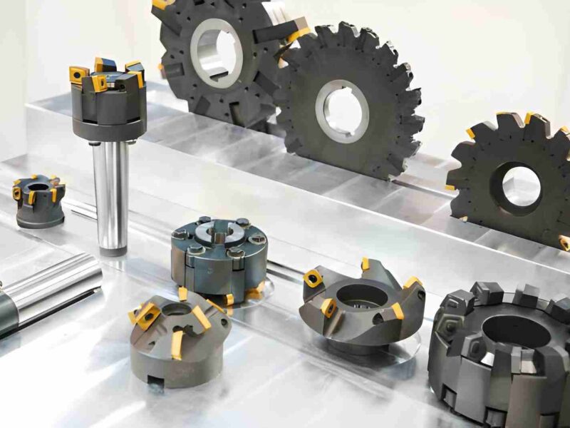
Types of Side Milling Cutters: Selecting the Right Tool
Selecting the right side milling cutter is essential for the machine tool to create parts that meet design specifications for surface finish, dimensional tolerance, and durability. Each type of side milling cutter is designed for specific combinations of part feature geometry, material, and production methods. The following describes the different types of cutters used in professional side milling applications:
| Cutter Type | Key Feature | Typical Application | Material Suitability |
| Plain Side Milling Cutter | Teeth on the periphery and both sides | Slots, shoulders, step milling | Steel, aluminum, cast iron |
| Half Side Milling Cutter | Teeth on one side and periphery only | Single-shoulder cuts, one-sided slots | Steel alloys, titanium |
| Staggered Tooth Side Milling Cutter | Alternating helix teeth for smooth cutting | Deep slots, interrupted cuts | Stainless steel, hardened steel |
| Interlocking Side Milling Cutters | Two matched cutters assembled together | Precise-width slots and keyways | All metals |
| Carbide-Tipped Side Milling Cutter | Carbide inserts brazed on body | High-speed, hard material milling | Hardened steel, cast iron, Inconel |
| Indexable Insert Side Mill | Replaceable carbide inserts | High-volume production, heavy roughing | Steel, cast iron, non-ferrous |
Half Side Milling Cutter: When One Side Is Enough
A half-side milling cutter is a special type of milling cutter with cutting edges on only one side and the outside diameter. Machinists use these types of cutters when cutting a feature on one side of a shoulder, and tool clearance will not allow the use of a full side milling cutter. Besides, it generates less cutting force than full-size milling cutters and is particularly effective for narrow shoulder milling requiring low deflection and tight tolerances.
Staggered Tooth Side Milling Cutters for Deep Slot Machining
Staggered tooth cutters have alternating right-hand and left-hand helical teeth to distribute the cutting forces more evenly. This helps to reduce chatter and also permits the manufacture of deeper slots without vibration. Thus, it makes them the preferred cutter choice for machining slots that are greater than twice the width of the cutter in stainless steel and alloy steel.
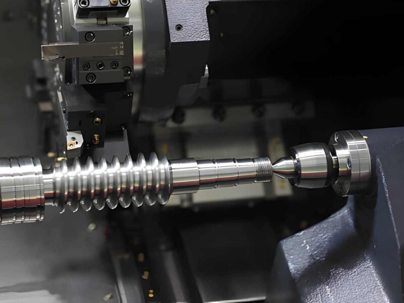
Side Milling Vs End Milling: Key Engineering Differences
Engineers will often compare side milling vs end milling to determine which approach would be best for a given milling operation. Although both processes can create slots or vertical features, side milling and end milling have very different mechanics, rigidity, and suitability for the application.
| Parameter | Side Milling | End Milling |
| Tool Engagement | Peripheral (radial) teeth engage workpiece side | End and peripheral teeth engage workpiece |
| Rigidity | Higher, large-diameter cutter with short overhang | Lower, long slender tool susceptible to deflection |
| Slot Width Control | Precisely set by cutter width (grinding to spec) | Controlled by tool diameter + programmed path |
| Depth Capability | Deep slots in one pass | Limited by flute length and L/D ratio |
| Surface Finish | Excellent on vertical walls | Good on all surfaces including floors |
| Machine Type | Horizontal or vertical mills | Primarily vertical machining centers |
| Setup Complexity | Arbor-mounted; setup is more involved | Simple collet or ER chuck mounting |
| Best Use Case | High-volume slot milling, keyways, straddle cuts | Complex 3D contouring, pockets, and general milling |
In mass production, machines will usually achieve more accurate slot widths with side milling. This is due to the fact that the cutter width for side milling is ground to specification, whereas with end milling, the tool requires programmed compensation for deflection.
Thus, the side milling is a better option for keyway slots, T-slots, and precision step features in aerospace and automotive parts. For example, if the tolerance on the slot width is less than ±0.025 mm, or if the slot is deeper than 3 times the diameter of the end mill, then side milling is best.
Side Milling vs Face Milling: Orientation and Surface Generation
Face milling and side milling represent two different orientations of material removal. Face milling generates flat, horizontal surfaces by using the end (face) teeth of the cutter to remove material. Besides, the machine’s cutter axis is perpendicular to the machined surface.
On the other hand, side milling generates vertical faces and slot geometries by using the peripheral teeth of the cutter to remove material while the cutter axis remains parallel to the machined surface.
For flatness and finish of horizontal surfaces, face milling will provide the best results and will often be the first machining operation on the surface of a large workpiece before carrying out subsequent machining.
Side milling will provide superior control of vertical wall dimensions and slot widths compared to face milling. Frequently, both operations may be performed in one setup. For example, face milling the datum first and then side-milling slots or shoulders relative to that datum.
Straddle Milling: Machining Two Parallel Faces
Straddle milling is a useful variation of side milling because it uses two side milling cutters built onto one arbor. It comes with a fixture or precision spacer in between them to mill both of the workpiece’s vertical faces simultaneously. The method guarantees parallelism because both faces will be cut with the same spinning tool at the same time. Typical uses of straddle milling include:
- Achieving precision across the flat dimensions of the two sides of hex cap head screws and nuts
- Creating the two parallel walls of the slots in the transmission shafts and spline parts
- Sizing both sides of a forged bracket in one step
- Producing both walls of a keyway on a motor shaft with tight tolerances.
The main advantage of straddle milling is that it eliminates the positional errors associated with moving the workpiece from one side to the other between two separate side milling operations. When the parts have tolerances of less than 0.02 mm for parallelism, straddle milling is the standard manufacturing process.
Side Milling Machine Setup and Critical Cutting Parameters
The proper configuration of the side milling machine setup is foundational to achieving dimensional accuracy and acceptable tool life. The following parameters govern the quality of a side milling operation:
| Parameter | Definition | Typical Range (Steel, Carbide Tool) |
| Spindle Speed (n) | RPM based on cutting speed and cutter diameter | 300 – 1200 RPM |
| Cutting Speed (Vc) | Surface speed at the cutter periphery | 80 – 200 m/min (mild steel) |
| Feed per Tooth (fz) | Material removed per cutting edge per revolution | 0.05 – 0.25 mm/tooth |
| Radial Depth of Cut (ae) | Radial engagement of the cutter with the workpiece | 5 – 30% of the cutter diameter |
| Axial Depth of Cut (ap) | Height of the side being cut | Up to 1.5× cutter width |
| Coolant Strategy | Flood, mist, or through-tool coolant | Flood preferred for steel; mist for aluminum |
Spindle speed is calculated using the formula: n = (1000 × Vc) / (π × D), where D is the cutter diameter in millimeters. For a 100 mm diameter carbide side milling cutter running at 150 m/min on alloy steel, the spindle speed is approximately 477 RPM.
Setting the correct feed per tooth is equally important because too low a setting can cause rubbing and accelerate tool wear, while too high a setting generates excessive cutting forces and risks catastrophic tool failure.
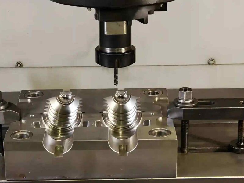
How Plain Milling, Form Milling & Angular Milling Relate to Side Milling?
Plain Milling (Slab Milling)
The plain milling using a flat end cutter on a horizontal workpiece produces a flat, smooth surface on the top of the workpiece. When using a plain milling cutter to create a surface, the workpiece is positioned in such a way that the cutter is in line with the workpieces and engages with its upper surface as opposed to being perpendicular to it (side milling). Therefore, plain milling establishes the datum for the side milling operation and then provides the basis for the side milling operation (perpendicular to the plain milling operation).
Form Milling
Form milling uses a profiled cutter whose teeth’ cross-section matches the desired feature geometry. The features can include T-slots, dovetail grooves, gear tooth forms, and fillet radii. The cutting mechanism is peripheral, the same as side milling, but the tool profile controls the feature shape rather than just the vertical wall. Form milling is the standard procedure for T-slot assemblies for machine tools, dovetail guides in machine tool construction, and rough-cutting of gear teeth before hobbing or grinding.
Angular Milling
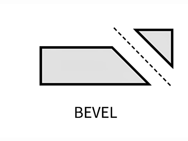
Angular milling uses a cutter with its teeth ground at a specific angle (commonly 45°, 60°, or some other angle based on the application) to cut either a chamfer, bevel, V-groove, or dovetail slot. For example, the manufacture of turbine engine disks within aerospace engineering will use an angular milling process to cut the dovetail slot into the outer rim of the disk to hold the blades in place. The angular precision of the dovetail slots will directly affect how well the blades are held onto the turbine engine disk and how much load is put on the blades when the turbine operates. The typical tolerances are ± 0.01° on the included angle.
Industrial Applications of Side Milling Across Sectors
Side milling is a basic machining operation across various high-precision industries. Below are examples of where side milling has its major applications:
| Industry | Application | Why Side Milling? |
| Aerospace | Turbine disk dovetail slots, structural wing rib pockets | Tight tolerances, difficult-to-machine alloys (Inconel, titanium) |
| Automotive | Crankshaft keyways, transmission shaft splines, gearbox slots | High volume, repeatable slot widths, and straddle milling efficiency |
| Oil & Gas | Valve body slots, connector keyways, flange features | Deep slot capability, hard material machining |
| Medical Devices | Bone screw slots, surgical instrument features | Precision, fine surface finish, biocompatible material handling |
| Industrial Tooling | Die components, jig, and fixture slots, T-slot tables | Form milling capability, accuracy to ±0.005 mm |
| Defense | Weapon component slides, rail slots, precision housings | Angular milling, tight bilateral tolerances |
Advantages and Limitations of Side Milling
Side milling offers several significant technical advantages, though engineers must also account for its limitations when selecting the process:
Advantages:
- Highly accurate dimensional measurements of slot widths; therefore, the cutter width is ground to specification eliminating toolpath compensation errors.
- Excellent surface finish on vertical walls; peripheral teeth will continuously engage for a smooth finish.
- Single-pass capability for machining even the deepest slots, using staggered-tooth or interlocked-cutter tooling.
- Assures parallelism between 2 machined surfaces when machining is completed by straddle milling.
- Large-diameter cutting tools allow for high material removal rates as many teeth will simultaneously engage the workpiece.
- Compatible with different materials, including hardened steels, titanium, aluminum alloys, and composites.
Limitations:
- Arbor setup is more complex and time-consuming than end mill mounting in a VMC
- Have limitations in flexibility to create complex 3D contoured features compared to 5-axis end milling
- Large-diameter cutters require fast machine spindles with enough torque and rigidity
- Need special equipment to restore a side milling cutter to its precise profile
- Chatter can occur at high axial depths of cut if the arbor support is too flexible.
Final Verdict
As long as the manufacturing world continues utilizing precision milling, side milling will remain an essential manufacturing technique that addresses one of the most common yet demanding engineering challenges: the creation of accurate, high-quality vertical surfaces and slots using one or more primary forms of milling process. The availability of numerous cutter types along with special cutting mechanics has made side milling the preferred method of creating all types of keyways, shoulder features, and deep slots.
At Premium Parts, our CNC milling capabilities encompass all forms of side milling, including creating prototype keyway slots or producing thousands of automotive transmission parts using straddle milling. Our team uses horizontal and vertical CNC machines with precision arbors and an extensive inventory of side milling cutters to manufacture side-milled components.
Whether your application requires plain milling as a pre-manufacturing step, straddle milling to ensure that two faces are parallel, or angular milling to produce precision dovetail features, PremiumParts has the manufacturing expertise to satisfy your needs.
Are you looking to create your parts using precision side milling? If so, contact PremiumParts today to schedule an engineering consultation and receive a quote.