A machinist once said that you can tell a lot about a machine shop by how they run their pockets. Apparently, it sounds like an odd thing to judge, but the more time you spend around CNC equipment, the more it makes sense.
Pockets are common enough that almost every operator has a routine for them, but at the same time, they are different enough that this routine varies drastically from one shop to the next.
Often, programs are tight, deliberate, and efficient. However, there exist others that consist of redundant passes and conservative feeds; they double the cycle time, but achieve no real gain. Overall, this gap comes down to understanding the toolpaths, cutting conditions, tool behavior, and how all of it interacts inside a confined cavity.
A poorly planned pocket leaves marks on the floor surface, on the tool, and on the clock, but a well-planned one is almost invisible. The part comes off the machine cleanly with no mismatched dimensions.
This guide covers all that you need to consistently produce well-planned pockets.
Introduction: What is CNC Pocket Milling
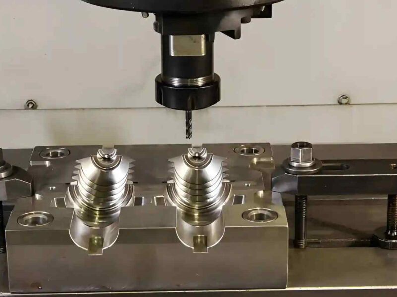
CNC pocket milling is a machining operation used to cut recessed cavities into a workpiece. The cutting tool moves within a defined boundary to remove material from the piece until the desired depth, shape, and surface finish is achieved. It is used to create internal cavities, and therefore relies on cutting the inside of a material, rather than using external cuts.
It is one of the most common operations in CNC milling, appearing across industries like general manufacturing, aerospace, automotive, and medical part production, all of which require a precise recessed geometry primarily. It is commonly employed on workpieces made of stainless steel, carbon steel, nylon, brass or copper.
Understanding CNC pocket milling properly goes beyond just the cut itself. Toolpath strategy, entry method, cutting parameters, and tool selection all play a direct role in how efficiently the pocket is machined and how accurately it comes out.
Defining Characteristics of CNC Pocket Milling
- The tool operates within a closed or semi-closed boundary, creating internal cavities inside the workpiece.
- Material is removed in successive depth passes called stepdowns through controlled toolpaths.
- Inside corners are always radiused, limited by the cutting tool diameter.
- Varies by flat-bottom pockets, contoured pockets, or stepped pockets.
- Floor finish and wall accuracy depend on toolpath selection and chosen cutting parameters.
Operations of CNC Pocket Milling
The geometry of a pocket, specifically, how its boundary relates to the rest of the workpiece, determines everything about the process: how the cutter gets into the material, how the CAM system clears it, the toolpaths and parameters needed.
Practically, CNC pockets comprise 3 major categories discussed below.
Closed Pockets
These are cavities where material surrounds them on every side. There is no external edge that leads to them. In this case, the programmer has to account for this from the beginning – they may use either a helical entry, a ramp move, or a pre-drilled hole to give the cutter a point to begin.
However, depth creates a challenge for the programmer and the tools, because the deeper the pocket, the harder it gets to clear chips and maintain consistent cutting conditions. Regardless, it always requires roughing and finishing passes at the end.
Closed pockets are very common in production work. From enclosures and mounting recesses to die cavities, they are used almost everywhere when a fully contained feature is a requirement of the chosen design.
Open Pockets
When at least one side of the cavity breaks through the part’s outer boundary, the pocket is considered open. The machining behavior and programmer’s decisions change considerably: lateral entry, which wasn’t an option for open cavities, now becomes possible, chip flow improves, and thus, a greater depth can be easily achieved. Overall, the programmer has much more flexibility in how the toolpath is structured.
Normally, CAM systems enter the tool from outside the part and cut inward, initiating the toolpath. Due to this, it often appears like a shelf or step rather than the traditional cavity. Open pockets are commonly used in weight-reduction features, access channels, and stepped profiles.
Island Pockets
Some pockets contain geometry that has to stay consistent. For example, a boss for a fastener, an alignment feature, or a structural rib. All of these traditionally sit inside the cavity, and the cutter has to work around them. The CAM system treats these internal regions as exclusion zones by creating toolpaths that clear the surrounding material without touching these islands.
However, as one may expect, complexity scales very quickly in island pockets because they require careful toolpath planning to avoid collisions and maintain consistent results.
Toolpath Strategies for Efficient CNC Pocket Milling
Toolpath selection is where pocket milling starts to get technical. Two setups cutting identical pockets in workpieces made of the same material can produce very different results in terms of cycle times, tool wear rates, or surface quality, simply because of how the path is structured. Usually, programmers rely on multiple strategies instead of one to get efficient CNC pocket milling.
Roughing and Finishing
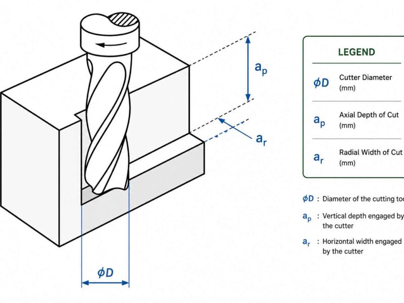
Productive pocket milling rarely happens in a single pass. The standard approach splits the operation into two distinct stages: roughing generally focuses on the material removal rate. It has to quickly create the pocket by removing all the excess material. Additionally, it deliberately leaves a ‘stock allowance’ of 0.2-0.5 mm on the walls and floors for finishing to then take over.
Next, finishing removes this allowance in controlled and lighter cuts to ensure accuracy and a smooth surface finish. Uneven walls, inconsistent dimensions, or visible cutter marks – all are likely to be visible if this step is avoided.
Z-Level Pocketing
It is the most straightforward approach: the cutter works at a fixed depth, removes the material, and then steps down to the next layer.
Spiral Pocketing
The cutter moves in a continuous inward or outward spiral rather than discrete layers as before. Overall, it supports direction changes and improved floor finish.
Trochoidal Milling
The tool follows a series of looping circular paths through the material, keeping the radial engagement low and consistent, particularly useful to reduce the tool load.
Adaptive Clearing
Sometimes also called dynamic milling, it continuously adjusts the toolpath to maintain a consistent chip load regardless of pocket geometry. The cutter follows smooth, flowing arcs, which reduces the cutting force.
Tool & Parameter Selection
Choosing the right parameters and tools is the next step after choosing the toolpath. In CNC pocket milling, the cutter stays engaged longer than in open profiling, which means poor choices can compound faster to show up in the part.
Tool Selection
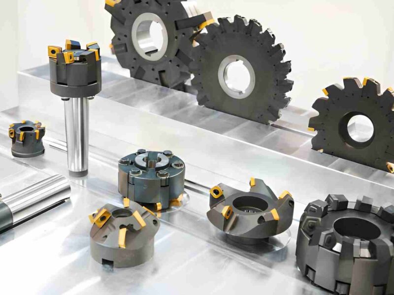
Flat end mills are the default tool for most of the pocket work. Generally, the flute count depends on material, so fewer flutes for aluminum because of chip clearance inside the cavity, but more flutes for steel because rigidity and wall finish become a priority. Similarly, internal corner radii set a hard limit on tool diameter since the cutter must fit the geometry.
Normally, in deeper pockets, tool reach must be taken into consideration as well. Rigidity drops off quickly as length increases, and deep pockets often force longer reach than ideal. Keeping the length-to-diameter ratio under 4:1 is a reasonable threshold to avoid chatter.
Parameter Selection
The chosen feeds and speeds should ideally target consistent chip formation. Rubbing generates heat and kills the tools early. Similarly, overloading through corners does the same thing, but faster.
Ideally, one should start with the manufacturer data, and then adjust the actual values from there based on depth, stick-out, and how the machine handles the cut.
For stepdown and stepover:
| Parameter | Suggested Range |
| Stepover | 30-50% of tool diameter |
| Stepdown | 0.5-1× tool diameter |
| Finish pass | 5-10% engagement |
Common Issues and Practical Solutions
| Issue | Solution |
| Tool deflection and chatter | Reduce length-to-diameter ratio, increase spindle speed, and reduce feed. |
| Poor surface finish | Run a finishing pass at roughly 5-10% engagement, and replace any worn-out tools. |
| Oversized pockets | Check tool runout before running, and verify values in CAM |
| Undersized pockets | Leave appropriate finishing allowance on walls, and verify actual tool diameter |
| Corner burnishing | Avoid sharp direction changes |
Conclusion
Pocket milling is quite straightforward in concept, but demands careful execution in practice. Toolpath strategy, tool selection, and parameter selection all directly affect the final result. As long as you get them right, your CNC pocket milling will run predictably regardless of complexity or material at hand.