A hole may have a position tolerance of 0.10 mm at Maximum Material Condition (MMC), but the actual tolerance of a finished part may be much larger. To find this real limit, first measure the hole produced relative to MMC, then add the difference back to the position tolerance. This is exactly the bonus tolerance principle behind MMC. It only works properly if, instead of the dimensions listed on the part, the actual geometry of the part is taken into account when the part is being inspected.
Introduction: What is Maximum Material Condition
MMC isn’t just another callout to check off for a drawing standard. Rather, it is the state where a feature holds the most material you’ll permit. For example, think of the fattest pin or the smallest hole. This defines the worst-case for fit, the moment when two pieces have the highest chance to clash. GD&T grabs this condition as its reference point to guarantee pieces will fit, no matter where the actual feature measures out inside its tolerance band.
All of this matters because specifying MMC on, for instance, a bolt hole pattern isn’t about satisfying a drawing standard; in fact, it is a functional guarantee for how the assembly behaves if every piece is at the worst edge of tolerance. If you’re throwing in tolerances without looking at the worst-case fit, you’re skipping the entire point of MMC.
The Bonus Tolerance Advantage
The real advantage of Maximum Material Condition (MMC) is bonus tolerance, and that’s exactly the reason why production teams care about callouts. When you tolerance a feature at MMC, the stated positional or orientation tolerance is just the starting point. As the actual manufactured size gets further from MMC, the allowed geometric tolerance increases by the same amount, so it is a straightforward, measurable trade-off between feature size and location.
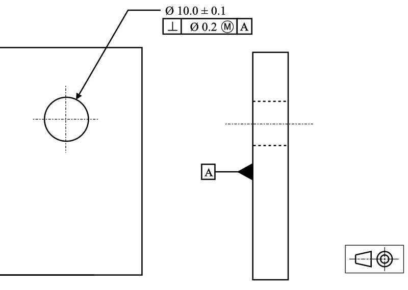
Consider a hole with a nominal diameter of 10 mm, a tolerance from 9.8 mm to 10.2 mm, and a positional tolerance at MMC of 0.1 mm. Here, MMC for the hole is 9.8mm, the smallest allowed size. If you make the hole exactly 9.8mm, your positional tolerance stays at 0.1mm. But if the hole is manufactured at 10.0mm, which is 0.2mm larger than MMC, your positional tolerance increases to 0.3mm. In other words, a larger hole gives you more wiggle room on position before you run into assembly or fit problems. There’s a physical logic here: a bigger hole can handle more positional error and still accept a fastener without trouble.
Therefore, the ⌀0.10 mm value in the feature control frame does not automatically become the final acceptance limit. The measured feature size should always be checked before the available position tolerance is finalised.
MMC in Additive Manufacturing vs. Traditional Machining
Bonus tolerance comes from the measured size of one feature. It has nothing to do with how that part compares to the rest of the batch. Acceptance and process capability are different questions, though. Acceptance asks if one feature meets its size and geometric requirements. Process capability asks if the process can keep hitting that requirement, part after part.
CNC turning and milling usually hold tight, predictable size variation across a run. That is a process capability strength, not something bonus tolerance needs to work on a given part.
Additive manufacturing runs into the process capability side more often, and the reasons shift by process.
- FDM parts can shift in size across a batch due to thermal shrinkage during cooling, uneven layer bonding, and nozzle wear. One measured part says little about the next one off the printer, so a single sample is not enough to lean on for bonus tolerance decisions.
- SLS parts can come out with holes shrunk and bosses grown relative to the CAD model, often from partially fused powder sticking to internal walls along with other process effects. SLS parts hold up well mechanically, but that does not mean their dimensions land where the model says they should.
- SLA parts tend to shrink and warp after UV curing, more so in large or thin-walled sections. Cured resin is also more brittle than machined or sintered material, so a feature sitting near its functional limit has less room for error. Designers should be careful about using the full bonus tolerance on these features.
Premium Parts runs process capability studies for FDM, SLS, and SLA, so if you are unsure how your parts are actually performing against spec, that is something we can help sort out.
How Does Virtual Condition Relate to MMC?
Virtual condition is the fixed boundary a feature is not allowed to cross, regardless of how its actual size and position vary within tolerance. For an internal feature, it is calculated as: Virtual condition = MMC size − position tolerance at MMC
Using the example above:
- Hole MMC = ⌀9.80 mm
- Position tolerance at MMC = ⌀0.10 mm
- Virtual condition = 9.80 − 0.10 = ⌀9.70 mm
This number does not change, even as the hole’s actual size and its available bonus tolerance shift within the allowed range. If the hole is produced larger than its MMC size, bonus tolerance increases and the allowable position tolerance grows with it. But no matter how size and position trade off against each other, the combined effect can never cause the feature to intrude past the ⌀9.70 mm boundary. This is what makes virtual condition useful for functional gauging and mating-part clearance: it tells a designer the worst-case space a feature will occupy, without needing to track every possible size-position combination individually.
Common MMC Interpretation Mistakes
- People often treat MMC and the maximum material boundary as interchangeable for every feature. However, this can only be done in extremely straightforward situations. The tolerance boundary will shift whenever some feature applies its own MMC modifier or when size and position tolerances accumulate. In such situations, it is essential to recalculate the final boundary.
- Often, bonus tolerances are applied based on a single measurement from one part of the assembly. This does not reflect the full variation, which is mostly seen in large-scale production, especially in additive manufacturing.
- MMC is also frequently confused with LMC (Least Material Condition). However, they are two different things. MMC protects against collisions at the worst-case largest pin or smallest hole. LMC, on the other hand, helps where the drawing needs to protect remaining material, such as minimum wall thickness or edge distance.
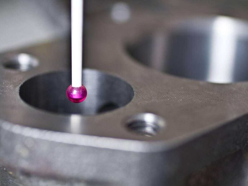
- You can’t just rely on a go/no-go gauge. A functional gauge is useful for checking the specified functional boundary, but it does not provide the same dimensional data as a CMM or variable measurement. Surface condition, local damage, and feature form may require separate inspection if the drawing controls them.
How to Inspect an MMC-Controlled Feature
Checking an MMC-controlled feature is a fixed sequence. Skipping a step or reordering it leads to an incorrect accept/reject decision.
- Record the actual produced size of the feature, for example, the hole’s measured diameter.
- Confirm that the measured size falls within the feature’s stated upper and lower size limits. If it does not, the part is rejected on a size basis.
- Subtract the actual measured size from the MMC size. For a hole, actual size minus MMC size gives the departure. This departure is the source of any bonus tolerance.
- The stated position tolerance at MMC (⌀0.10 mm in the earlier example) is added to the departure calculated in step 3. This sum is the total available position tolerance for this specific part.
- Record the feature’s actual position deviation, separate from its size.
- If the actual position deviation from step 5 is equal to or less than the total available tolerance from step 4, the feature passes. If it exceeds it, the feature is rejected.
Conclusion
MMC is an essential tool in GD&T, particularly when the size and location of a feature have to both work together to ensure the parts actually fit together. However, for this to happen, bonus tolerance must be calculated following the same procedure a part was made from.
If you’re still confused, Premium Parts can help review your current MMC callouts and drawing requirements. Send us your drawings or CAD file, and our team will reach out shortly.
FAQs
How is MMC different from LMC?
MMC describes the feature containing the most material, whereas LMC is the exact opposite – the feature containing the least material.
When is MMC useful on a position tolerance?
MMC is commonly used for mating features such as bolt holes and locating pins when departure from the maximum-material size creates additional clearance that can be used as geometric tolerance.
Does virtual condition change if the hole is produced larger than its MMC size?
No, even though a larger hole increases the available bonus tolerance and position tolerance, the virtual condition itself stays fixed.