LMC (Least Material Condition) is a term used in Geometric Dimensioning and Tolerancing (GD&T) to describe the size of a feature at which it has the least material but is within desired tolerances. LMC is used to control the functional requirements of holes, shafts, slots, and tabs. It is defined by minimum wall thickness, minimum retention of material, and strength.
LMC has specific boundaries for the different types of features:
- Holes and internal features: LMC occurs at the largest permissible diameter. This is because a larger hole removes more material around the feature.
- For shafts, pins, and external features: LMC occurs at the smallest diameter allowed because a smaller shaft has less material.
The term is often confused with Maximum Material Condition (MMC), which is the opposite boundary to LMC:
| Modifier | Hole (internal feature) | Shaft (external feature) | Primary use case |
| LMC | Largest permissible diameter | Smallest permissible diameter | Minimal wall thickness and material preservation |
| MMC | Smallest permissible diameter | Largest permissible diameter | Assembly fit and interference control |
When designing precision components whose primary focus is to prevent material loss rather than interference with the part in contact, the engineering team at Premium Parts often cites LMC.
Symbol and GD&T Drawings
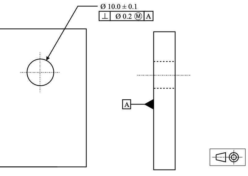
In engineering drawings, LMC is indicated by the circled letter L following the tolerance value in a feature control frame. A feature control frame that invokes LMC includes, in order:
- Geometric feature symbol: usually position, since position is the most common characteristic paired with LMC.
- Tolerance zone value: the numeric tolerance that applies when the feature is at its least material condition, the diameter or width limit where the least amount of material remains.
- LMC modifier: the circled L, placed directly after the tolerance value.
- Datum references: the datums, in order of precedence, from which the tolerance zone is measured.
Example callout: position | ⌀0.25 | (L) | A | B
To read this callout correctly, four things must be checked in unison, not just the tolerance value:
- The controlling geometric property (position).
- The type of modifier applied (LMC, not MMC or RFS).
- The datums and their stated order (first A, then B).
- The feature the callout is attached to, since the tolerance zone value and the bonus tolerance it earns only make sense relative to that feature’s actual size.
The modifier tells the inspector what condition the feature must be measured against. With LMC, the stated tolerance applies only when the feature is at its least material boundary. As the feature departs from that boundary and gains material, a bonus tolerance is permitted, and the allowable tolerance zone grows accordingly.
Swapping the LMC modifier for an MMC modifier does not simply reverse a symbol. It changes the condition against which the feature is measured and the direction in which bonus tolerance is earned. Whether that swap is correct depends on the design intent behind the callout. For example, whether the function being controlled requires wall thickness to be preserved (LMC) or assembly clearance to be preserved (MMC). A drawing reviewer must confirm the modifier matches the design intent, not just that a modifier is present.
Datum features can also carry their own LMC modifier, which shifts how that datum is located during inspection. This is a distinct topic from feature control frame modifiers and is covered separately.
If you’re still confused, reach out to us at Premium Parts. We utilize a drawing review checklist, based on ASME Y14.5, for any parts marked with LMC callouts, since a single symbol error changes acceptance criteria for the entire production run.
Bonus Tolerance
Bonus tolerance is the extra amount by which the position or the geometry of a feature gets to differ from its specified limits. This depends on how far the size of the feature produced in manufacturing has moved towards the MMC boundary from the LMC boundary. The minimum level of assurance that can be guaranteed is the stated tolerance value, and is applicable only when the feature is located exactly at its LMC.
The calculation of bonus tolerance follows three steps. The example below uses a hole with the following specifications:
- Hole size range: 10.0 mm to 10.5 mm
- LMC for the hole: 10.5 mm (the larger hole size, since a larger hole removes more material and leaves the least material remaining)
- Position tolerance stated at LMC: ⌀0.20 mm
Steps:
- Determine the LMC size: this is the boundary value stated on the drawing. For this hole, LMC = 10.5 mm.
- Record the actual produced size: measured with calibrated instruments. For this hole, the actual size is 10.3 mm.
- Calculate the bonus: the difference between the LMC size and the actual produced size. 10.5 mm − 10.3 mm = 0.20 mm bonus.
Adding this bonus to the position tolerance stated at the LMC gives the total tolerance permitted for the part: 0.20 mm + 0.20 mm = ⌀0.40 mm.
This method exists because a hole produced smaller than its LMC size (10.3 mm instead of 10.5 mm) removes less material and leaves more material surrounding the hole. That extra surrounding material creates room for the hole’s position to shift further without reducing the wall thickness below the design minimum. As the produced size moves closer to MMC, the available bonus tolerance increases; at LMC itself, the bonus is zero and only the stated tolerance applies.
Common LMC Interpretation Mistakes
- Reversing the bonus tolerance direction is another point of error. Some designers and inspectors default to the more common MMC size relationship (largest hole, smallest shaft is MMC) instead of LMC’s opposite relationship (largest hole, smallest shaft is LMC), which leads to an error in the bonus tolerance calculation.
- Applying LMC only when fit, and not material, is the concern. It does not guarantee that the design-mating fit is obtained, as the bonus tolerance logic of an LMC does not prevent an interference the way MMC does.
- Mismeasuring or skipping the actual produced size altogether is an error that can cause either result in accepting an out-of-tolerance part or rejecting a conforming one, since a bonus tolerance relies on a measurement deviation from the boundary of the LMC.
- Not providing the LMC modifier when referencing a datum feature, particularly when it is required, results in the datum location being fixed instead of one that shifts with the datum’s own produced size, resulting in inspection results that may be opposite of what the design intent was.
Premium Parts addresses such potential errors through drawing reviews to ensure that the modifier has been selected against the intended functional requirement for both production release and quoting. Reach out to us now, and book your free drawing review.
Conclusion
Least Material Condition is a GD&T modifier that helps determine the maximum and minimum limits of a tolerance at the boundary of a feature that contains the least material. Typically, it is accompanied by positional tolerances to ensure that a minimum wall thickness, edge distance, or engagement strength is achieved.
The right application comes down to determining whether you need LMC or MMC. LMC is useful when the geometric requirement needs to protect a minimum amount of material around a feature. The drawing must identify the correct feature size boundary, modifier, and applicable geometric tolerance, because this greatly reduces the chances of misinterpretation.
If a design requires certain materials to be left in place, Premium Parts helps with review and manufacturability analysis of the drawings, ensuring that LMC callouts align with the design intent, and that there are no manufacturing surprises.
FAQs
When should LMC be applied instead of MMC?
LMC should be applied when the design’s functional requirement is preserving minimum material, such as wall thickness or edge distance, rather than controlling fit between mating parts.
What is LMC for a hole?
For holes specifically, LMC is the largest permissible diameter.
Can LMC be applied to a datum feature?
Yes, when applied to a datum feature, the datum’s effective location shifts within the datum feature’s own tolerance range at its least material boundary, affecting inspection setup. Premium Parts can review drawing packages to confirm this modifier is applied correctly where required.