Precision in CNC machining begins long before the spindle rotates. The rigidity of the workpiece, the ability of the machine to suppress vibration, and the ability of the machine to accurately repeat the location of a given datum are directly related to the clamping method(s) used during setup.
Regardless of whether a machine shop is machining a titanium aerospace bracket, a hardened steel die component, or an involute gear profile with sub-micron runout control requirements, the workholding strategy will largely determine whether the final part falls within specification or ends up as scrap. Inadequate clamping can result in chatter, datum shift, and micro-deflection, all of which contribute to dimensional inaccuracy, inferior surface finish, and reduced tool life.
This guide will provide the user with an overview of CNC clamping methods currently being employed in the modern machine shop, from standard vise arrangements to advanced hydraulic and vacuum systems, as well as the engineering data to substantiate any recommendations made.
Why CNC Clamping Method Selection Is a Critical Engineering Decision
When selecting a methodology for clamping, there is more than just the need to keep the part secured due to its clamping force, cutting force, and how stiff the material is where it is being clamped. The need to keep the part secure must also take into consideration the time to do so, as well as the stress and distortion on the part when delivered to the cutter, which will be created from clamping. A clamping device selected improperly may create just as much variance in the CNC-machined product as a worn spindle bearing.
The basic requirement of a CNC work-holding system is to achieve a six-degree-of-freedom (6-DOF) constraint without over-constraining the component. In other words, all three degrees of translation and all three degrees of rotation must be eliminated, all while preventing any redundant constraints that would rock or induce stress to the product.
In modern manufacturing, as batch sizes get smaller and as parts’ complexity increases, a work-holding system should also allow fast changeover. Each of the next sections will cover the most common clamping devices and methods to choose the best clamping method for a given situation.
CNC Clamping Method Overview
| Clamping Method | Typical Force Range | Best For | Accuracy Level |
| Mechanical Vise | 5 – 50 kN | Prismatic parts, short runs | ±0.01 – 0.05 mm |
| Hydraulic / Pneumatic Clamps | 10 – 100 kN | High-volume production | ±0.005 – 0.02 mm |
| Vacuum Fixtures | 0.5 – 5 kN | Thin-wall, non-ferrous sheet | ±0.003 – 0.01 mm |
| Magnetic Chucks | Variable (up to 15 kN/dm²) | Ferrous grinding and milling | ±0.002 – 0.005 mm |
| Collet Chucks | Up to 30 kN radial | Turned parts, bar stock | ±0.002 – 0.005 mm TIR |
| Custom Fixtures / Tombstones | Design-specific | Complex, multi-face parts | ±0.005 – 0.015 mm |
Mechanical Vise Clamping: Setup, Force Distribution, and Limitations
In CNC milling, the machine vise is the most commonly used work-holding fixture. While its design may appear basic, the clamping action of a precision vise is created by a lead screw that applies significant lateral and vertical clamping forces depending on the geometry of the jaw.
A typical 6” milling vice can produce between 15 – 25 kN of clamping force when a normal operator torque is applied to the lead screw and is usually sufficient for use with aluminum and mild steel.
When clamping, it is important for engineers to take into account the phenomenon of jaw lift, which is where the movable jaw tends to lift the workpiece when clamping force is applied. Jaw lift is a function of the moment arm created by the distance from the centerline of the lead screw to the face of the movable jaw.
It is very common for standard vises to have a jaw lift range of 0.02 to 0.08 mm when clamping a workpiece, which will adversely impact Z-datum accuracy. Therefore, the most accurate way to machine precision parts is to use vises designed specifically to minimize jaw lift, or by clamping one set of jaws and using downforce from strap clamps for additional clamping.
Step Jaw and Soft Jaw Applications
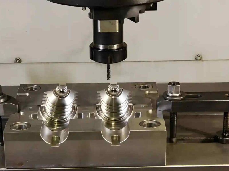
Using Step Jaws allows the workpiece to be placed below the top face of the jaw, increasing the depth of jaw engagement and decreasing the lift of the jaw. Using soft jaws, which can be made of either machinable aluminum or plastic and used as inserts, enables the operator to develop custom part-specific profiles to distribute the clamping load over a larger area of contact.
This design feature is particularly advantageous when clamping near-net-shape castings or forged blanks because it eliminates the possibility of achieving proper parallel jaw-to-jaw contact.
Boring soft jaws to a specific diameter ensures that the arc of contact will be equal to at least 120 degrees, ensuring uniform distribution of radial clamping force and preventing deformation of the part when clamping very thin-walled cylindrical workpieces. Boring soft jaws requires a dedicated setup procedure, i.e., the jaws must be bored in place, under simulated clamped conditions, before clamping the workpiece, to eliminate any error accumulated from the previous setup of the fixture.
Hydraulic and Pneumatic Clamping Systems for High-Volume CNC Production
For CNC production with high volume, hydraulic and pneumatic clamps deliver consistent and controlled torque and eliminate the variable of torque application from operator to operator.
Hydraulic clamps work best with high-pressure hydraulic lines of 50 – 350 bar, which deliver highly repeatable clamping loads at each clamp location at the same point in time. This eliminates the occurrence of dimension scatter often associated with multiple operators assembling parts in a repetitive process.
Pneumatic clamps use lower pressure (5 – 8 bar), typically found in most machine shops when using standard air, so they deliver a lower clamping force. However, pneumatic clamps can complete the task of clamping and unclamping very quickly. Hence, they are also very well suited for high-cycle automated assembly lines where the loading of the part is done by a robotic arm and the fixture needs to clamp and unclamp in less than two seconds.
Hydraulic Fixture Design Considerations
When designing hydraulic fixtures, engineers take into account the following parameters:
- Clamp Approach Angle with Respect to Cutting Force Vector: Ideally, clamps should be positioned within 15 degrees of opposing the primary cutting force direction.
- Hydraulic Circuit Sequencing: Multiple clamps must be actuated in the proper sequence to avoid part movement.
- Oil Temperature Compensation: The viscosity of hydraulic fluid decreases as the temperature rises, which affects both the response time and the consistency of force.
- Fail-Safe Design of Hydraulic Clamps: Spring return clamps will hold the workpiece in place after a loss of pressure and thereby prevent the workpiece from being ejected during operation.
- Seal Life and Coolant Ingress: Ingress of coolant into the hydraulic circuit has been noted as one of the leading causes of early seal failure.
Hydraulic vs. Pneumatic Clamping: Engineering Comparison
| Parameter | Hydraulic | Pneumatic |
| Operating Pressure | 50 – 350 bar | 5 – 8 bar |
| Max Clamping Force | Up to 100 kN | Up to 15 kN |
| Actuation Speed | 1 – 5 seconds | < 1 second |
| Force Repeatability | ±0.5% of set pressure | ±2 – 5% (compressible) |
| Risk of Part Ejection | Low (spring-return available) | Higher (air loss = release) |
| Cost | Higher (pump, manifolds) | Lower (shop air) |
| Best Application | Heavy cutting, aerospace, die machining | Light machining, automation cells |
Vacuum Fixture Clamping: Holding Thin-Wall and Non-Ferrous Parts
Vacuum Fixtures use the differential between atmospheric pressure and a 0.85 – 0.95 bar below ambient pressure (typically) to create a distributed clamping force on the underside of the workpiece. As such, the maximum theoretical clamping force of the vacuum fixture is equal to the effective sealing area times 0.1 N/mm².
For example, a vacuum zone measuring 300 x 200 mm will provide a maximum of 6 kN holding force; therefore, while this is much smaller than offered with mechanical methods, it is still sufficient for applying light finishing cuts to aluminum sheet, PCB substrates, and carbon fiber panels (due to the ability to use mechanical clamps causing either crushing of the part or blocking tool access).
Design of vacuum fixtures requires careful attention to seal groove design. A seal groove for O-ring seals should be machined to 70 – 80% of the O-ring cross-section compression at the seating depth, with the groove width approximately equal to 1.3 times the O-ring’s nominal diameter. In addition, before initiating any production run, vacuum decay rate testing should be performed. This test will measure pressure decay over 60 seconds without any workpiece positioned in the fixture to ensure that there are no signs of seal wear or surface contamination.
Vacuum Fixtures in Involute Gear Blank Machining
Vacuum fixtures are a great choice for face operations on involute gear blanks made from aluminum alloy. They are an extra good option when using collet and mandrel setups because they eliminate radial runout from errors in collet concentricity. The part is sitting flat against a precision-ground reference surface to maintain 0.005mm of parallelism from the top to the bottom face of the part, which is critical for producing accurate involute gear teeth in subsequent hobbing and milling operations.
Magnetic Chuck Clamping for Ferrous Parts and Grinding Operations
Permanent and Electropermanent Chuck Types
If you’re using ferrous workpieces, electromagnetic and permanent magnetic chucks are great choices for providing a distortion-free clamp during surface grinding, jig grinding, or in CNC milling applications. The holding forces for a permanent magnetic chuck range from about 8 to 15 N/cm², making this type of chuck ideal for grinding passes that have axial cutting forces in the 200 to 500 N range that are present in creep-feed grinding.
An electropermanent magnetic chuck combines the energy efficiency of a permanent magnet with the ability to control the holding force of an electromagnetic chuck. The magnetically charged and demagnetized electropermanent magnetic chuck does so from a momentary current pulse without the use of a continuous power supply to maintain the holding force, which is very useful in case of power interruptions.
Residual Magnetism and Demagnetization Requirements
Residual magnetism captures an engineering limitation of magnetic chucks and will remain in the work after it is removed from use. Therefore, it should be eliminated before mating parts (assembly) and specifically in precision parts where ferromagnetic chips could become attracted to and contaminate bearing/seal surfaces. Bench demagnetizers utilizing 50 – 60 Hz AC and a magnetic field strength > 50 Oe are effective with a working load range of up to 50 kg.
Collet Chucks and Expanding Mandrels: Concentric Work-Holding for Rotational Parts
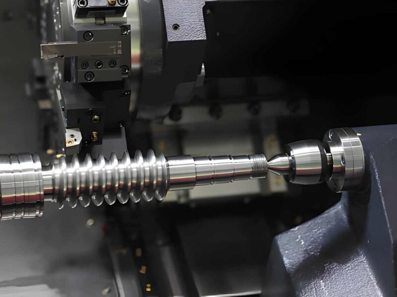
Collet chucks provide a means of holding a workpiece concentrically. This is important when machining or fabricating timestamped workpieces or bar stocks. Compared to the typical three-jaw scroll chuck’s total indicated runout (TIR) of 0.01-0.03 mm, collet chucks can achieve TIR values between 0.002 and 0.005 mm. This level of accuracy makes the use of a collet chuck the preferred method for holding precision-turned components, such as shafts, bushings, and involute gear blanks that require tight concentricity between the bore and the tooth form pitch cylinder.
In CNC machining centers, ER collets, the ISO 15488-compliant standard for collet types, are the most commonly used because they are compatible with both the spindle tool holder and the fixture collet chuck. The ER collet has a clamping range that extends at least 1 mm below the nominal bore size, and each collet size covers a range of 0.5 mm to 1 mm in diameter.
Expanding mandrels grip the internal bore of the workpiece from the inside, allowing full access to the outer diameter. By using an arbor with a precise taper that engages either a precision collet or a hydraulic expanding sleeve, it is possible to achieve repeatability within better than 0.003 mm TIR over multiple loadings.
Custom Fixtures and Tombstones for Complex CNC Work-Holding
Custom fixtures can justify their cost when part configurations do not meet the needs of standard work-holding or if machine cycle times can be improved through multiple operations being performed on an ongoing basis, versus having to create new fixtures for each process. Tombstones provide multiple clamping points on vertical aluminum beams that may hold multiple machined objects at one time in a horizontal machining center (HMC) while providing access for the spindle to machine all surfaces of each object during a single pallet rotation.
The main structural design consideration for a tombstone is rigidity to withstand the total of all torques produced by the cutting forces acting at a distance from the center of the pallet. Finite Element Analysis (FEA) is now routinely used during the design phase of a tombstone to evaluate whether or not deflection at the far end of the clamped area will be less than 0.005mm based upon worst-case cutting conditions. Tombstones made of Aluminum 6061-T6 have proven to have sufficient stiffness for most low-volume machining applications. Still, steel-fabricated tombstones are typically needed for large-volume machining operations of steel and cast iron (greater than 2kN of cutting force per clamp), where the potential for greater bending moment loads is produced.
Frequently Asked Questions
What is the most accurate CNC clamping method for precision parts?
For finished items, collet chucks and hydraulic expansion mandrels will give you the highest degree of accuracy. Both of these methods can provide total indicated runout (TIR) values ranging from 0.002mm to 0.005mm. Vacuum fixtures and precision magnetic chucks are comparable for flat items; however, they will not distort the parts due to point clamping forces while being clamped.
Can vacuum fixtures hold parts during aggressive CNC milling cuts?
A vacuum fixture is suitable for light finishing and semi-finishing; however, the maximum cutting forces that can be used with this method are typically limited to 1kN to 2kN. To achieve the necessary clamping force for a heavy cut when working with aluminum or steel, the use of either mechanical clamps or the combination of vacuum and mechanical clamps is required.
How does the clamping method affect the involute gear machining accuracy?
The clamping method used during the manufacture of involute gears has a direct effect on the runout (wobbling), datum shift, and spacing between teeth on an involute gear. When using an expanding mandrel or a hydraulic collet chuck, both of these methods will reduce the amount of wobble at the pitch cylinder (the primary reference point for determining the accuracy of the teeth on an involute gear).
Conclusion
CNC clamping methods are the foundation of precision manufacturing, and not an afterthought. Each workholding method requires the designer/engineer to consciously balance tradeoffs between clamping force, accuracy, cycle time, and part access. Engineers who understand these tradeoffs will choose the most appropriate method from the outset, leading to fewer setup iterations, reduced scrap rates, and lower costs of tools.
To begin any CNC project, Premium Parts completes a workholding review. Our team ensures that the workholding or clamping strategy will support a part’s required dimensional specifications, whether it’s a simple mounting bracket or a high-accuracy involute gear profile manufactured to the DIN quality specification of 6 or finer.