Many people still view CNC machining as a metal-only process. In fact, plastic machining runs on the same machines, using controlled cutting to form functional parts. Stock material turns into housings, brackets, insulators, bushings, and sealing components. Materials like ABS, nylon, POM, PTFE, and acrylic react differently during cutting operations. Some soften near heat, some cut with stable chips, and some shift at thin walls. Therefore, you must control cut speed, chip flow, and tool pressure to match material behavior to avoid edge melt, burrs, and size drift.
At Premium Parts, plastic parts are machined for prototypes, assembly checks, and production use. Tool paths and clamping setups change based on how each plastic responds during cutting. This keeps features usable during assembly without extra fitting work.
This article explains how CNC plastic machining works, which materials suit different applications, what issues appear during cutting, and how process choice affects final part function. So, keep on reading.
What Is CNC Plastic Machining?
Plastic CNC machining cuts solid plastic stock using programmed tools to form the required shape and features. The machine follows defined tool paths to remove material in steps until the final geometry is reached. This method is used for dimensionally critical parts that need clean surfaces and direct adjustment during production without creating molds.
The process works on engineering plastics. For example, ABS, nylon, POM, PTFE, and acrylic are some of the common plastic types. Each material behaves differently under the tool during cutting. For instance, some plastics soften with heat, and some produce long chips, while some crack at thin sections. Therefore, cutting speed, feed rate, and tool type must match the material to prevent deformation, surface damage, and poor fit during assembly.
How CNC Plastic Machining Works
Plastic CNC machining follows a fixed sequence where each step directly affects the final part condition. The process moves from design to cutting, then finishing, and inspection. Every stage controls shape, fit, and surface outcome.
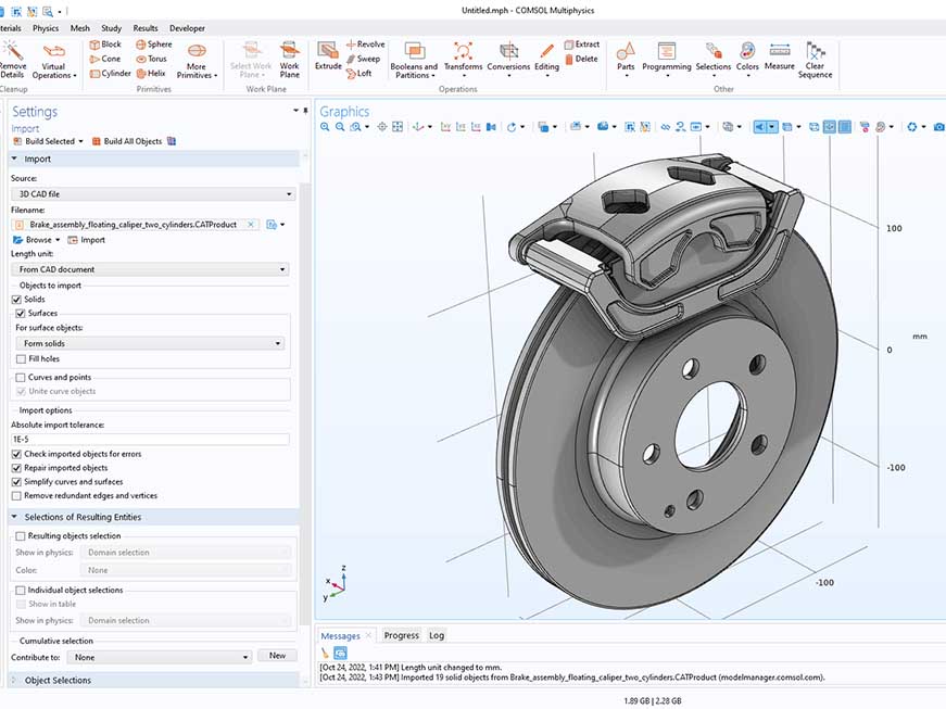
Create the CAD Model and Toolpaths
The process starts with a CAD model that defines all part features. CAM software converts this model into toolpaths for machining. Cutting speed, feed rate, and tool selection are set based on plastic type to control cutting behavior.
Prepare and Secure the Plastic Stock
Plastic stock is placed on the machine table before cutting begins. Clamps or fixtures hold the material in position during machining. Proper holding prevents movement, while support under thin areas reduces bending during cutting.
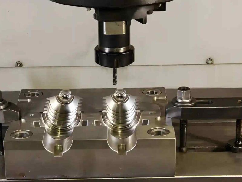
Run Rough Cutting to Form the Shape
The machine removes bulk material to create the basic shape of the part. Chip flow needs control since heat can build up during continuous cutting. Stable cutting settings help avoid surface marks and edge softening.
Perform Finishing Passes for Final Features
After roughing, the tool removes a small layer of material to form the final features. Edges, holes, and mating surfaces take shape in this stage. This step controls how well the part fits during assembly.
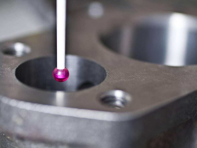
Inspect and Finish the Part
The finished part goes through dimension checks and surface review. Burrs get removed from edges before use. The part then moves forward for testing or assembly if it meets design requirements.
Types of Plastics Used in CNC Machining
CNC machining uses engineering plastics that respond in different ways during cutting. Some cut clean with stable chips, some soften under heat, and some deform under tool pressure. Material choice depends on load conditions, movement, chemical contact, and electrical use in the final part.
ABS (Acrylonitrile Butadiene Styrene)
ABS cuts smoothly and keeps its shape during machining. It produces controlled chips and supports stable surface formation without heavy cracking. It suits general machining tasks with moderate structural demand.
ABS is used in enclosures, brackets, and prototype parts. It fits electronic housings and test components that go through repeated assembly during development and design validation.
Nylon (PA6 / PA66)
Nylon absorbs load during movement and handles friction in sliding contact. During machining, it can react to heat and slightly shift shape, so controlled cutting is required to avoid edge distortion.
Nylon is used in gears, bushings, rollers, and wear parts. It performs in moving assemblies that involve repeated contact and continuous mechanical motion.
POM (Delrin / Acetal)
POM machines are clean and produce stable chips during cutting. It holds shape well and supports fine features without breaking under tool pressure. It suits parts with controlled movement and a tight assembly fit.
POM is used in gears, valve parts, and snap-fit components. It performs in mechanical systems that require smooth motion and repeated operation without surface wear buildup.
PTFE (Teflon)
PTFE is soft and reacts quickly under tool pressure. Cutting must stay light to avoid edge deformation and uneven surfaces. It also handles chemical exposure without surface change.
PTFE is used in seals, gaskets, and chemical system parts. It supports sealing applications and fluid handling components exposed to aggressive chemicals.
Acrylic (PMMA)
Acrylic produces clear edges during machining, but can crack under sudden tool force. It requires steady cutting to avoid surface chipping and internal stress marks.
Acrylic is used in display panels, covers, and transparent guards. It fits visual inspection parts and protective enclosures that need clear visibility.
Polycarbonate (PC)
Polycarbonate handles impact but reacts to heat during machining. Cutting must stay controlled to avoid surface marks and internal stress lines.
PC is used in safety shields, machine covers, and protective housings. It fits parts exposed to impact and mechanical protection requirements.
HDPE (High-Density Polyethylene)
HDPE cuts with soft chips and low resistance during machining. It can shift under tool force, so proper holding is required to avoid movement during cutting.
HDPE is used in tanks, guides, and sliding components. It performs in chemical handling systems and low-friction mechanical movement parts.
UHMWPE (Ultra-High Molecular Weight Polyethylene)
UHMWPE resists wear but shifts under machining force if not fixed properly. It needs strong support during cutting to maintain shape.
UHMWPE is used in conveyor parts, wear strips, and guide systems. It works in continuous motion systems with high surface contact.
PVC (Polyvinyl Chloride)
PVC machines easily but reacts to heat during cutting. Excess heat affects edge quality, so controlled machining is required for clean results.
PVC is used in pipes, insulation parts, and structural components. It fits fluid transport and electrical protection systems.
PET (Polyethylene Terephthalate)
PET maintains a stable shape during machining and produces stable edges. It supports detailed features without major deformation under cutting load.
Usually, PET is used in mechanical supports, insulation parts, and housings. It fits assemblies that require stable geometry during repeated use.
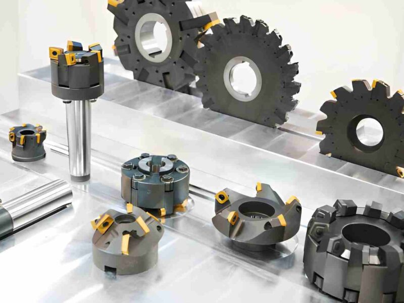
CNC Machining Techniques for Plastic
Plastic machining uses different cutting methods based on axis movement, tool control, and part geometry. Each technique removes material in a specific direction and affects surface formation, chip flow, and edge condition. Selection depends on part shape and functional use.
3-Axis Milling
3-axis milling moves the tool along X, Y, and Z directions while the plastic stays fixed on the table. The tool cuts flat surfaces, pockets, and basic 3D shapes in step-by-step passes. Chip buildup needs control since plastics soften under heat during continuous cutting.
3-axis milling is used for housings, brackets, and covers with flat and stepped features. It also supports prototype parts that need quick design changes and internal cavities without complex setups.
4-Axis CNC Milling
4-axis milling adds rotation around one axis, usually the X-axis. The part rotates while the tool continues cutting, which allows access to multiple sides without repositioning. This reduces setup changes and keeps alignment consistent between faces.
4-axis milling is used for cylindrical housings, connector bodies, and parts with features on multiple sides. It fits components that need side holes, grooves, or curved surface machining in one setup.
5-Axis CNC Milling
5-axis milling moves the tool across X, Y, Z, and two rotational axes. The tool reaches angled surfaces directly, reducing repositioning. It also helps control tool contact on complex shapes.
5-axis milling is used for complex housings, medical parts, and precision assemblies with angled features. It fits components that need curved surfaces, deep pockets, and multiple orientation features in one process.
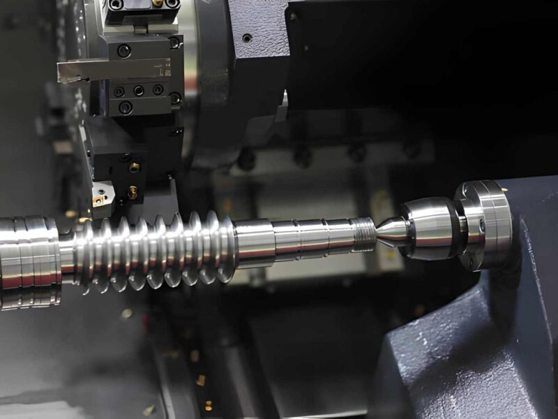
CNC Turning
CNC turning rotates the plastic stock while the tool moves along the axis. The tool removes material from the outer diameter and can also form internal bores. Stable clamping is required to avoid vibration during rotation.
Turning is used for bushings, rollers, spacers, and cylindrical connectors. It fits parts that need round geometry and smooth contact surfaces for sliding or alignment.
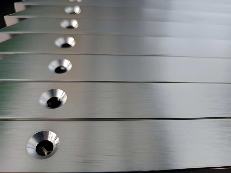
CNC Drilling
CNC drilling pushes a rotating tool along the Z-axis into the plastic to create holes. Feed rate must stay controlled to avoid heat buildup and melting at the entry point. Chip removal affects the hole shape and surface inside the bore.
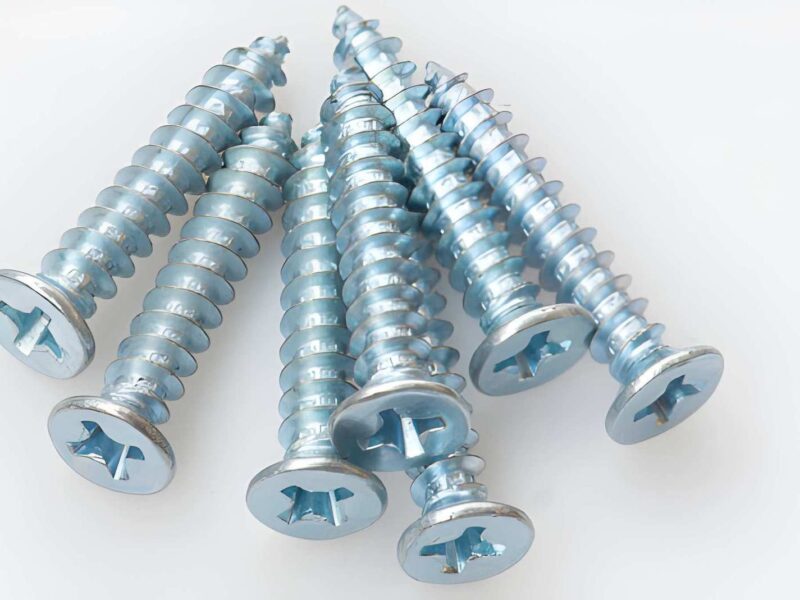
Drilling is used for mounting holes, alignment points, and fastener locations. It supports assembly parts that connect different components using bolts, pins, or screws.
CNC Routing
CNC routing moves a high-speed tool along X and Y with light depth cuts in Z. It works well for sheet plastics where large flat parts are required. Tool path control prevents edge chipping during fast movement.
Routing is used for panels, enclosures, signage parts, and large covers. It fits flat plastic components that need fast cutting and simple edge profiles.
Benefits of Using Plastics for Machining Over Metals
Plastic machining removes material with a lower cutting force compared to metals. The tool stays under a lighter load, so tool wear reduces and cutting speed increases. Heat buildup also stays lower, which removes the need for heavy coolant use in most cases.
Plastic parts reduce overall assembly weight. This helps in moving systems, handheld equipment, and enclosures that do not need metal stiffness. In many builds, lighter parts also reduce stress on fasteners and supporting structures.
Design changes stay simpler with plastics. Geometry can be adjusted without long tooling preparation cycles. This supports testing stages where parts change after each iteration.
Plastics also avoid corrosion issues seen in metals. Moisture and chemicals do not create rust or surface breakdown. This makes them suitable for fluid handling parts and electrical insulation components.
Post-processing stays limited in many cases. Edges come out clean after machining, so extra grinding or coating steps are reduced. This shortens total production time.
Material cost stays lower for many engineering plastics compared to aluminum or stainless steel. This makes them practical for prototypes, fixtures, and functional parts that do not need metal-level strength.
Limitations And Challenges Of CNC Plastic Machining
Plastic machining delivers good results in many applications, but material behavior sets clear limits. Heat response, internal stress, and wear characteristics directly affect how the part performs during cutting and after installation.
Heat Build-Up During Cutting
Plastic reacts quickly to cutting heat. When speed is too high, the material starts to soften at the contact zone and loses edge definition.
This condition also affects chip flow. Chips stay near the tool instead of clearing away, which increases friction and disturbs surface finish during continuous cuts.
Parts Shift After Machining
Many plastics carry internal stress from the stock material. Once machining removes material, this stress releases and causes slight movement in the part.
Thin or long components show this more clearly. Flat surfaces can bend slightly, and hole positions may shift after resting for some time.
Limited Strength Under Load
Plastic parts have lower resistance under continuous or concentrated load. Thin sections and threaded areas deform earlier when the force increases.
During repeated assembly cycles, contact surfaces start to loosen. Threads lose grip, and joints require stronger design support to stay functional.
Wear In Moving Contact
Repeated sliding contact slowly removes material from the surface. These changes fit and reduce smooth movement over time.
Gears, bushings, and sliding guides show this effect first. Clearance increases gradually, and motion becomes less controlled as wear continues.
Chip Control Issues
Some plastics produce long and flexible chips during machining. These chips wrap around the tool and interfere with clean cutting.
When chips stay in the cutting zone, heat builds up, and surface finish becomes uneven. Stable chip removal is required to maintain cutting consistency.
Low Temperature Resistance
Many plastics soften when exposed to elevated temperatures. Heat from nearby equipment or operating conditions affects dimensional stability.
This becomes more visible near motors or heat sources. Over time, parts lose shape accuracy in these areas and require material selection adjustment.
Useful Tips For Machining Engineered Plastics
Plastic machining is sensitive to heat, chip control, and tool condition. So, you must keep cutting energy controlled and avoiding material softening during engagement.
Control Cutting Speed And Feed
Plastic reacts quickly when the cutting temperature rises. If speed stays high during long passes, the surface starts to soften and loses edge definition.
Feed control changes how chips break away from the cut. When chips stay long and continuous, they rub back on the surface and create marks.
Stable chip breakup is important in thin sections. Once heat builds up in one area, dimensional drift becomes visible near the edges.
Use Sharp And Suitable Tools
The tool condition decides how clean the cut stays. A dull edge increases friction and pushes heat directly into the material.
Single-flute tools work better in softer plastics since they clear chips faster and reduce clogging at the cutting zone.
Chip buildup on tool edges changes cutting behavior. Once material starts sticking, surface finish becomes uneven within a few passes.
Secure the Workpiece Properly
Plastic parts respond to clamping pressure during machining. If support is uneven, thin areas start bending under the tool load.
Flat contact under the workpiece helps reduce vibration during cutting. Without it, small shifts appear along the tool path.
Clamping force should stay balanced. Excess pressure leaves marks, while weak holding causes movement during finishing passes.
Manage Chip Removal And Heat
Chips left in the cutting zone raise the local temperature. This affects surface quality and increases friction between tool and material.
Air flow helps keep the cutting area open. It prevents chip buildup around the tool and improves visibility during machining.
Coolant use depends on the material type. Some plastics react to moisture, so dry chip removal is often more stable than heavy cooling.
What Drives CNC Machining Cost
CNC machining cost depends on how fast the material is removed, how the tools behave, and how much preparation each part needs. Plastics and metals react differently during cutting, so the same design can change cost structure based on material choice and process load.
Material Removal Rate
Material removal rate affects how long the machine runs for each part. Plastics cut faster with lower resistance, so cycle time stays short. Metals remove slowly due to higher cutting force, which increases machine time and total cost.
Tool Wear and Replacement
Tool wear changes cost through maintenance and tool replacement frequency. Plastics cause low tool wear since the cutting force stays light. Metals increase tool wear due to heat and cutting resistance, which leads to more frequent tool changes.
Machine Time and Cycle Duration
Machine time directly controls production cost per part. Plastic machining completes cycles faster due to simpler cutting behavior. Metal machining takes longer because of slower feeds and multiple passes for stable cutting.
Setup and Fixturing Effort
Setup time affects cost before cutting starts. Plastic parts need simpler fixturing since cutting forces stay low. Metal parts need rigid setups to handle vibration and force during machining, which increases preparation time.
Post-Processing Requirements
Post-processing adds extra cost after machining. Plastic parts often need light finishing, like deburring. Metal parts may require additional steps such as polishing, surface treatment, or coating before final use.
CNC Machining Cost Comparison: Plastics vs Metals
Plastic and metal machining follow different cost patterns because the material behavior changes cutting speed, tool wear, and post-processing effort. Plastics remove faster and need less tool force, whereas metals demand slower cutting and stronger tooling. These differences directly affect the total machining cost.
Cost Comparison Table
| Factor | Plastic CNC Machining | Metal CNC Machining |
| Material cost | $ | $$ to $$$ |
| Machining time | $ | $$ to $$$ |
| Tool wear | $ | $$ to $$$ |
| Setup complexity | $ | $$ |
| Post-processing | $ to $$ | $$ to $$$ |
| Overall cost | $ to $$ | $$ to $$$ |
Applications of Plastic CNC Machining
Plastic CNC machining produces parts where weight control, fast design changes, and simple processing matter. It supports prototypes, short runs, and functional components. Therefore, it fits engineering work that changes during development rather than fixed mass production.
Electronic Enclosures and Housings
Plastic machining creates housings for control units, sensors, and electronic modules. These parts need openings for ports, switches, and cable routing. Machining helps adjust these features when internal layouts change during testing.
ABS and polycarbonate are commonly used since they hold shape during assembly and handle screw tightening. As a result, they reduce cracking around fastener zones when design loads change during installation.
Mechanical Fixtures and Jigs
Plastic fixtures hold parts during drilling, assembly, or inspection. They reduce surface damage compared to metal setups and are easy to handle during repeated use on the shop floor.
Nylon and POM work well in these fixtures. They handle repeated contact at holding points. Therefore, wear stays low even during long production cycles.
Medical and Laboratory Components
Plastic machining produces fluid channels, test fixtures, and device housings. These parts need clean internal paths for controlled fluid movement and handling. Machining helps create these features directly from design models.
PTFE and acrylic are used because they handle chemical exposure and keep surfaces stable during repeated use. Generally speaking, these materials suit controlled environments where contamination control is required.
Automotive Interior and Functional Parts
Plastic CNC parts include brackets, clips, and interior supports. These parts change during design stages, so machining allows quick updates without tooling delay.
ABS and polycarbonate are used because they handle vibration and impact inside assemblies. As a result, parts stay functional during repeated testing and installation cycles.
Electrical and Insulation Parts
Machined plastic parts separate conductive elements inside electrical systems. These include spacers, mounts, and insulation blocks. Machining keeps spacing consistent inside compact assemblies.
Nylon and PVC are used because they maintain insulation behavior under load. Therefore, they support stable separation between electrical components during assembly and use.
Work With Premium Parts for CNC Plastic Machining
Plastic CNC machining needs correct material selection, stable cutting control, and proper process planning. Small changes in setup can affect fit, surface condition, and final part function. At Premium Parts, we support plastic part manufacturing from the prototype stage to low-volume production with clear engineering review before machining starts.
You can upload your CAD file through our system. Our team checks material choice, tool paths, and manufacturability before production. This step helps reduce machining issues and improves part fit during assembly without extra rework.
We support industries like automotive, aerospace, medical, and electronics, where plastic parts must perform in real assembly conditions. Each project gets process control from machining to final delivery, with a focus on function and consistency across batches.
If you need plastic CNC parts for testing or production, share your design and start your project with Premium Parts.
FAQ’s
Which plastic works best for tight mechanical assemblies?
POM and nylon perform well in tight assemblies because they hold shape during cutting and support repeated contact without early wear.
Can plastic CNC parts replace injection-molded parts?
Plastic CNC parts work well for prototypes and low-volume runs. Injection molding suits higher volume production after design validation.
Why do some plastic parts change shape after machining?
Internal stress in the raw material is released after cutting. This causes slight movement in flat or thin sections over time.
How do engineers choose the right plastic for machining?
Material selection depends on load, movement, chemical exposure, and temperature conditions in the final application.
How can the CNC machining cost be reduced?
Cost reduces when part design avoids unnecessary complexity. Simple geometry reduces machining time and tool movement. Material choice also affects cost, since plastics machine faster than metals in most cases.