Involute gears dominate the power transmission segment of industry since their tooth profiles (the unwinding of a tangential line around a stationary base circle) produce a constant velocity ratio and a predictable line of action throughout mesh engagement. In comparison to other tooth profiles like a cycloidal or circular arc, the involute geometry can tolerate small center distances without compromising the contact ratio or the overall. This is why involute geometry formed the basis of ISO 1328, AGMA 2000, and DIN 3962 worldwide standards for gears.
In CNC manufacturing, one can only produce an involute gear if the module, pressure angle, profile shift coefficient, and tooth flank finish are tightly controlled, because if there is a deviation as small as 0.02 mm on the form of the involute, it will produce noise, uneven load distribution, and cause premature wear of the tooth flank due to the operating conditions. This guide covers the entire engineering workflow for precision gear manufacturing, from generating an involute profile to the design equations for gears, methods of drawing gear CAD files, machine strategy for CNC machining, and tips and tricks for producing precision gears.
What Is an Involute Gear and Why Does the Profile Matter?
The tooth profile of an involute gear is formed from a base circle and a string that is wound around it. The shape is obtained as the string unwinds. The involute is a consistent mathematical form for the tooth flank and allows for a constant line of action throughout the entire engagement of teeth. This constant line of action is what gives the gear profile its fundamental advantage of having a constant velocity ratio between two meshing gears at all points on the tooth flank.
As such, there are two critically important points in the design process to consider:
- Base Circle Diameter: The base circle diameter controls the involute shape. Changing the angle of pressure changes the size of the base circle, which in turn creates a new shape for the entire flank.
- Profile Accuracy: The precision of the profile during manufacturing will determine if the actual contact behavior will match that which was designed. A gear may appear to be manufactured correctly; however, the tooth surface will cause vibration, noise, or premature wear if the tooth surface is even slightly different than the theoretically correct shape.
The standard pressure angle of most industrial involute gears today is 20°, but in some cases, where gear loads are heavy, a 25° pressure angle is being used to provide a larger root thickness. In older machines, the 14.5° pressure angle was used widely but is now typically found to be replaced by greater than 20 degrees because of the larger, deeper root section, and it’s typically more sensitive to changes in the center-to-center distance.
Involute vs. Cycloidal and Other Gear Profiles
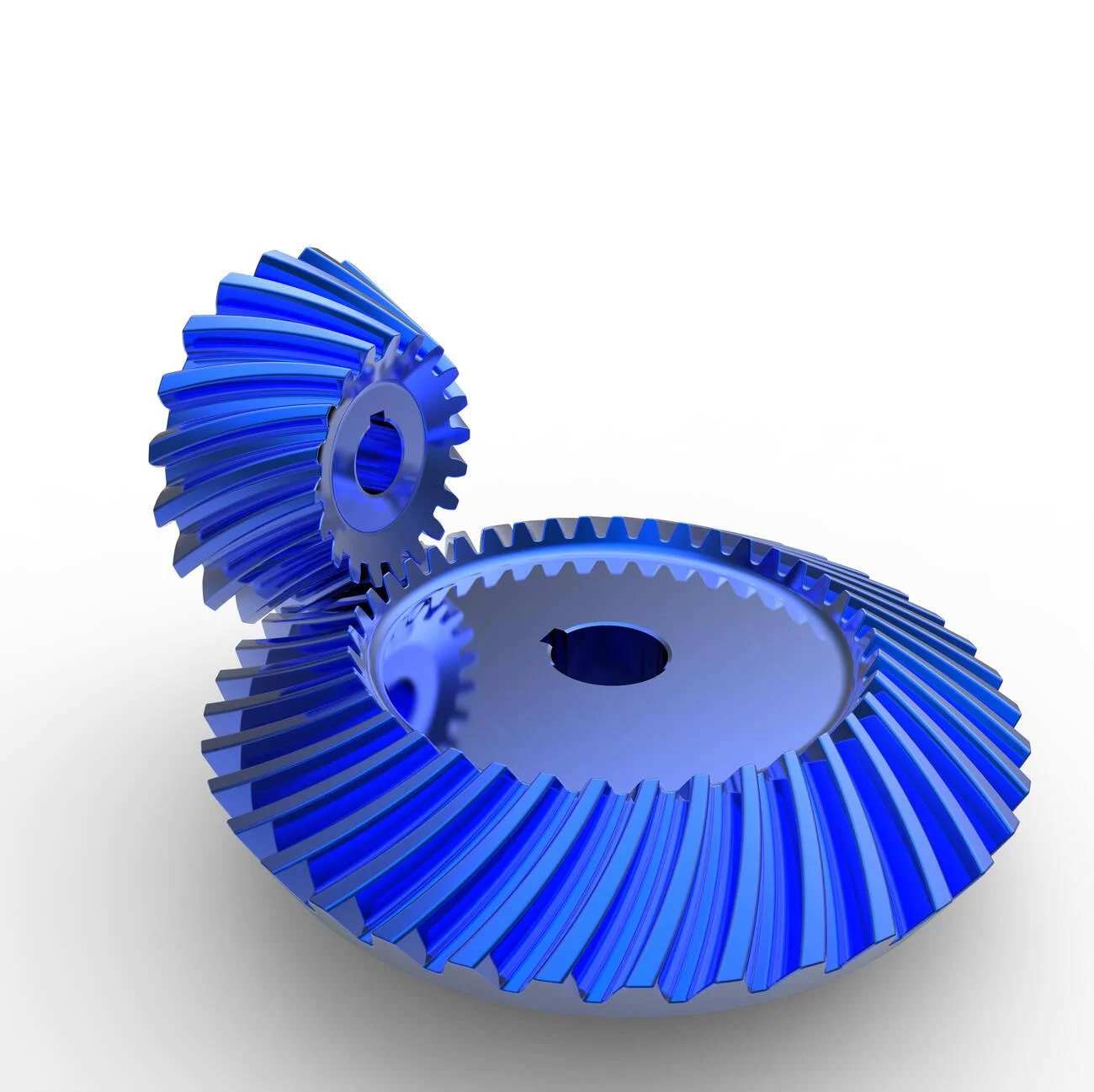 Blue anodized crown and pinion spiral bevel gears
| Parameter | Involute Gear | Cycloidal Gear | Circular Arc Gear |
| Line of action | Constant (straight) | Varies with rotation | Varies |
| Center-distance sensitivity | Low – small variation tolerated | High-precision spacing required | High |
| Manufacturing method | Hobbing, shaping, milling, grinding | Specialized cutters required | Specialized cutters required |
| Tooling standardization | High – one hob covers many modules | Low – profile-specific tooling | Low |
| Inspection method | Standardized (involute checkers, CMM) | Application-specific | Application-specific |
| Common application | Gearboxes, reducers, drives, CNC | Clocks, pump rotors | High-load aircraft gearing |
| Interchangeability | High within the same module/pressure angle | Limited | Limited |
Involute gears are the dominant gear type in the industrial manufacturing sector because, with an involute gear cutter (gear hob), one can cut many tooth-count variations of the gear using the same gear hob (from cutter to gear) as long as you maintain the constant module and pressure angles. Consequently, this characteristic is also why involute geometry has become a foundation for all worldwide gear manufacturing standards (ISO 1328, AGMA 2000, DIN 3962) and is the reason why all CNC machining facilities engaged in making gears set their manufacturing process based on the use of involute gears.
Involute Gear Profile Design: Core Parameters and Engineering Equations
Key Design Parameters
An involute gear drawing begins with a core set of values that dictate all other dimensions, and when they are not correct, there will be errors through machining, constructing, and checking.
| Parameter | Symbol | Typical Range | Engineering Impact |
| Module | m | 0.3 – 50 mm | Controls tooth size, cutter selection, and load capacity |
| Number of teeth | z | 6 – 400+ | Determines pitch diameter and undercut risk |
| Pressure angle | φ | 14.5°, 20°, 25° | Shapes flank geometry and bearing load |
| Face width | b | 6m – 12m (typical) | Affects load distribution and axial rigidity |
| Addendum | a | 1.0 × m (standard) | Controls tooth height above the pitch circle |
| Dedendum | d | 1.25 × m (standard) | Controls tooth depth below the pitch circle |
| Profile shift coefficient | x | −0.5 to +0.5 | Used to eliminate an undercut or adjust the center distance |
Changing the module tooth strength directly impacts the pitch diameter, spur gear outer diameter, and spur gear root clearance. It also impacts the CNC milling cutter radius, as well as the number of passes needed for cutting out the tooth space. An engineer who considers any of these variables independently (e.g., changing just the module without regard to root clearance/fitment with housing bore) will create an interference condition that will not manifest itself until final assembly.
Undercut Risk and Profile Shift Correction
Cutting involute gears with large toothed racks leads to the generation of undetermined exteriors, created by an undercut. The most important point at which an undercut will begin occurs when the number of teeth starts to go below a certain threshold value based on the size of the gear, commonly referred to as the minimum number of teeth (z_min). For a gear with 20° of pressure angle, z_min = 17 teeth. When any given rack cutter has fewer than 17 teeth, it will remove some material from the bottom of the tooth, weakening that part of the tooth and distorting the involute geometry.
In engineering terms, the solution is a “profile shift,” which means radially displacing the cutter away from the gear blank before cutting. A positive profile shift (x > 0) creates external modulation, effectively removing undetermined exteriors from all teeth on a gear to eliminate inconsistencies between teeth due to undercuts.
In essence, anytime you are designing a set of gears (especially when they are going to be used at high RPM with z_min <17), x will be calculated and determined during design, rather than being strictly an after-the-fact type of issue or refinement to the design.
Drawing an Involute Gear Profile: CAD Workflow and Common Errors
Constructing the Profile from Base Circle
To create an involute using a straight line, utilize the old methods of drafting the involute gear profile. Using a straight line as a point of reference that rolls along the base circle of the gear, and using that line to create the involute using drafting tools. In most manufacturing CAD environments today, one can complete this entire operation without a physical representation of the gear. The majority of the parametric modeling software applications, such as CATIA, Inventor, or NX, have a built-in mechanism for generating gears; i.e., gear generators/equation-driven curve functions from module, tooth count, and pressure angle inputs to develop the involute shape.
The correct drawing sequence for a spur involute gear:
- Determine base circle, pitch circle, total outside diameter of gear, and total root diameter of gear.
- Calculate the involute curve from the base circle outwards until reaching the total outside diameter of the gear.
- Create the opposite side of the involute, creating the opposite tooth flank through the mirroring function in the CAD application utilized.
- Calculate the width of the tooth space at the pitch circle (= pi x m/2 for normal gears)
- Include root fillet of approximately (0.38 x m) for normal full-depth teeth.
- Array all of the tooth geometry around the center point at 360/z
- Conduct a contact ratio check. The contact ratio should be > 1.2 to ensure smooth engagement of gears.
CNC Machining Drawing Requirements
When submitting a gears CAD file to a computer-controlled machining facility, you should include more specifications than when submitting a generic CAD model of a machined component. The specification required for your gear is outlined below in the following table; it details the minimum drawing callout requirements necessary for accurately producing the gear:
| Drawing Element | Required Detail | Why It Matters |
| Module | Numeric value (e.g., m = 2) | Controls cutter selection |
| Pressure angle | Degrees (e.g., 20°) | Defines tooth flank geometry |
| Number of teeth | Integer value | Sets pitch diameter and spacing |
| Tooth accuracy grade | ISO 1328 or AGMA class | Defines allowable profile and pitch deviation |
| Surface finish on the tooth flank | Ra value (μm) | Determines finishing requirement |
| Span measurement / over-pin measurement | Calculated value + tolerance | Primary dimensional inspection method |
| Root diameter | Minimum value + tolerance | Controls cutter depth |
| Profile shift coefficient | x value if non-standard | Affects tooth thickness and center distance |
Common Drawing and Modeling Errors
In the manufacturing industry, frequent mistakes are common with involute gear drawings. A few of the constant problems are:
- Incorrect root fillet radius: A small radius fillet will create high-stress concentration on the root (where a gear tooth is held by its radius) and won’t produce an involute profile. If the fillet is too high, it will take material away from the base circle.
- Omitting a profile shift callout: If the involute profile travels down the length of the gear teeth with a distance of x, the machinist must know this shift. Otherwise, the standard tooth thickness is produced on the gear and will not mesh properly.
- Wrong Span Measurements: Span measurements must be made using the completed tooth profile on the gear that is being measured. If the span dimension is obtained from a generic print without being verified against the property of the specific gear, it does not produce correct tooth-to-tooth measurements.
- Pressure Angle Mismatch: Matched gears must have the same pressure angle in order to generate a proper contact surface. Mating a 20° pressure angle with a 14.5° pressure angle provides the wrong geometry of tooth contacts, even if the pitch diameter of both gears is matched.
- Contact Ratio Ignorance: If the contact ratio of the two gears is below 1.0, there is a time when no gear tooth will be in contact with the other; and when the tooth makes contact with each other, there is an impact load to produce damage to the gears and assembly.
CNC Machining Tips for Involute Gears
Selecting the Right Machining Process
Manufacturing process selection has a significant influence on profile precision, cycle time, and costs. The appropriate choice will depend on factors such as production run size, needed precision level, type of teeth to be manufactured, and equipment used in producing the gears.
| Process | Best Application | Accuracy Range | Notes |
| Gear hobbing | External spur and helical gears, medium to high volume | ISO 5 – ISO 8 | Most efficient for production; continuous cutting |
| Gear shaping | Internal gears, close-shoulder features, small batches | ISO 5 – ISO 8 | Slower than hobbing; better for restricted geometry |
| CNC milling (form milling) | Prototypes, low volume, large module gears | ISO 8 – ISO 10 | Flexible; each tooth is cut individually |
| CNC milling (5-axis) | Complex gear geometry, bevel gears, custom profiles | ISO 7 – ISO 9 | Higher setup cost; excellent for development |
| Gear grinding | Post-heat-treatment finishing, precision drives | ISO 3 – ISO 6 | Corrects distortion; high surface quality |
| Wire EDM | Flat spur gears, thin sections, hardened material | ISO 6 – ISO 8 | Good for hardened blanks; slow cycle time |
Toolpath Strategy for CNC Milled Involute Gears
CNC machined with a series of CNC milling machines for the manufacture of involute gears, the common practice for prototyping or large gear modules, and bespoke one-off gears is as follows: to achieve the least amount of profile error and best surface finish:
- For roughing, mill with a full radius end mill using a radial offset of 0.15mm to 0.25mm of finish stock on the cut value. The use of climb milling in the roughing operation will eliminate the build-up of chips on the cutting tool during the rough milling operation and provide a consistent chip size during the finish.
- For the finish involute tooth flank, use a dedicated form cutter. The form cutter used is designed to the exact parameters of the gear module and gear pressure angle. A standard end mill will not replicate the involute shape without multi-axis interpolation.
- To ensure the highest possible profile accuracy in the finish, use 5-axis interpolation in the final pass. The tool will tilt to maintain a consistent contact angle across the tooth flank, thereby eliminating the existence of ever-present faceting due to the discrete step-over operations of the 3-axis.
- Use extreme care in controlling the removal of chips from the tooth space. Chip entrapment is an inherent property of narrow and deep geometry; therefore, it is especially problematic with fine-pitch gears. Eliminating chip re-cutting can be achieved by using high-pressure coolant directed at the exit point of the cutting tool and/or by using repeated peck cycles through the teeth.
Heat Treatment and Distortion Management
Surface hardening after rough machining is necessary for almost every structural gearing application. Carburizing and case hardening to between 58 – 62 HRC on the surface of the tooth is the normal requirement for gears that operate under a continuous load. However, heat treatment will induce some dimensional movement to the gear and typically leads to approximately 0.05 to 0.15 mm in the teeth due primarily to their size and cross-section geometry.
For gears that will meet some ISO tolerance of either 6 or greater after heat treatment, the process has the following workflow:
- Rough machine: Keep an amount of 0.5 to 1.0 mm of grinding stock on the tooth flanks and on critical bores.
- Heat treat: Use carburizing, hardening, and tempering to specification.
- Stress relief: If there is significant distortion in the loaded profile, use a straightening or stress-relieving process to alleviate some of the distortion.
- Finish grind: Grind tooth flanks to the intended profile and surface finish.
- Inspect: Perform 100% inspection of the helical tooth profile using the full involute tooth profile, as well as by pitch measurement and runout verification.
While the grinding of gears after heat treatment can save time on gears that are required in a short amount of time, it would never be beneficial to skip the post-heat-treatment grinding process due to the reduced serviceability of distorted profile gears when compared to the cost associated with grinding them.
Surface Finish and Running Behavior
The tooth flank surface roughness affects two major areas of the operation of gears: (1) noise levels and (2) wear rates, especially during the running period when the lubrication system has not fully developed its lubricating films.
The typical hobbed gear will achieve a Ra of 1.6 to 3.2 microns on the tooth flank; a ground gear can achieve a Ra of 0.4 to 0.8 microns, which is the optimal surface finish for gearbox applications that operate at speeds greater than 3,000 RPM or in noise-sensitive applications.
Poorly finished tooth flanks have significant amounts of micro-asperities on the surface, which will generate heat and metallic debris due to contact between them during initial operation.
If the lubrication film does not fully separate the two surfaces, especially at the pitch where the sliding velocity is the lowest, then adhesive wear will begin, which will accelerate the wear of the tooth profile.
For high-speed or precision servo drive gears, adding a lapping or superfinishing process after the grinding step reduces tooth flank surface roughness to between Ra 0.1 and 0.2 microns, which can help extend the useful life of the gears by a measurable amount.
Frequently Asked Questions
Q: What is the minimum tooth count for an involute gear without undercut at 20° pressure angle?
17 is the minimum number of teeth for full-depth cuts at a 20° pressure angle. If a gear has fewer than that, undercutting will occur at the base of the teeth unless the cutter has been shifted positively away from the centerline to create the involute profile.
Q: Can CNC milling produce involute gears to the same accuracy as gear hobbing?
Using five-axis CNC mills, we can achieve accuracy levels for individual gears equal to hobbing. However, cycle times per tooth for milled gears are generally longer than for gears produced on a hobbing machine.
Thus, CNC milling is an acceptable option for prototypes and low-volume parts, but becomes uneconomical for quantities greater than approximately 30 pieces.
Q: Why does center distance affect involute gear mesh quality?
The center distance is the distance between the pitch circles (or where the pitch diameters meet) of two mating (mesh) gears. If the actual dimension deviates from what it was designed to be, then the contact point on the tooth flank changes, affecting both the backlash and effective pressure angle.
Involute gears offer better tolerance for smaller amounts of deviation than do cycloidal gears. However, larger deviations will also affect how the load is distributed among the teeth and may lead to tip interference or a reduction in tooth contact ratio.
Conclusion
The involute used as the preferred tooth pattern in precision mechanical engineering arises from the fact that it supports the process of manufacturing, evaluation of production tools or equipment, and allows manufacturing tolerances to apply for assembly purposes across production environments.
The design profile of the involute is not only a geometric consideration, but also all design parameters: selecting the module, selecting the pressure angle, and selecting profile shift.
Premium Parts has a complete necessity for involute gear CNC machining, including the review of gear geometry for DFM, access for tooling and undercut risk, selection of proper cutting process for accuracy, and quantity/volume of gears being produced, evaluating the material use with the process for heat treatment.
We consistently replicate involute gear profile quality from batch to batch and will build your next involute gear according to your specifications. Ready to begin machining your next involute gear? Contact us now to receive a quick engineering review quote.