Choosing the right tap drill size to achieve the optimum size of thread taps is crucial. However, it’s not as easy as it seems. Usually, it’s considered a major problem for many design manufacturers and thus end up having stripped threads and weak connections. Do you get frustrated by getting it wrong, or by having bad threads? Then don’t worry, there’s a simple solution.
In determining the right tap drill size, it is necessary to consider the tapped hole type and intended material. In the majority of the thread forms, the tap drill should produce a hole; a depth of 75% of the thread. Since it’s important to mitigate reconnecting issues between the two components, over and over again. Printed circuit boards (PCBs) may use fine or coarse threads and normally need modifications over time.
So, after a basic understanding, let’s take a look deeper at the different types of threads you can use for different nominal sizes.
What Is a Tap Drill?
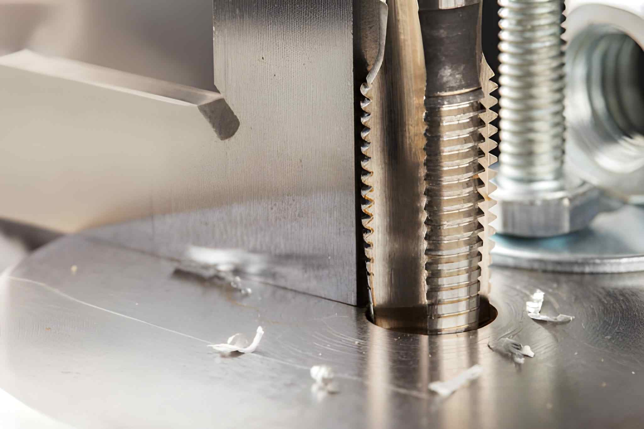
Tapping Tool
Image Description: A close-up view of a tapping tool showing its sharp threads and flutes designed for creating internal threads in metal parts.
A tap drill makes a hole designed to take a particular thread during tapping. The hole diameter is as important as the thread engagement degree because the overall formation of the connection is of concern. Moreover, the tap drill size is often undersized for the full thread diameter.
So, the tap can cut the threads into the material. In most routine threading processes, the tap drill size is selected to be about 75% of the thread depth for adequate thread formation and strength. In addition, the correct tap drill size depends on the type of thread and the material being tapped—whether coarse, fine, or metric.
Why It’s Important To Keep the Correct Tap Drill Size?
Here are the key benefits of ensuring accurate tapping:
Optimum Thread Engagement
A correct tap drill size enables the tap to thread deeper enough to provide a firm hold to connected parts. This makes it possible for the threads to interact well with the fastener and leads to strong joints. Additionally, a well-specified hole increases the load-bearing capabilities of the threaded connection to higher-limit loads.
Prevents Stripped Threads
An oversized hole can result in threads that do not engage correctly. If the hole diameter is too large, the threads may not have enough material to engage, resulting in poor fastening. In addition, when you select the correct size of the tap drill, you can be in a position to get a better and more effective hold.
Minimizes Tool Wear and Breakage
Employing the wrong size of drill increases pressure on the tap and the drill bit. Thus, it can also increase wear and tear. If you use a correctly sized tap drill, the tools slice through the material with minimum resistance. So, there’s less chance of the tool breaking or chipping.
Optimizes Tapping Efficiency
If the hole made is the same size as the tap size, the tap can be cut perfectly and in an even manner to avoid binding and seizing. In addition, the right size reduces the force required to tap the hole to complete the process in a shorter turnaround.
Promotes Thread Accuracy
The right hole size is moreover, significant for accurate threads to be formed. When using a specific tap drill you can ensure the thread line will be made correctly. Thus, you can minimize misalignments and uneven pressure circumstances of failures.
How to Calculate Tap Drill Size
To calculate the correct tap drill size, use the following formula:
Tap Drill Size = Major Diameter – Thread Pitch
- Major Diameter: Outer diameter of the threaded fastener (bolt or screw).
- Thread Pitch: It defines the distance between threads (for metric threads, It is the pitch; for imperial threads, it’s the number of threads/inch).
For example:
For a M10 x 1.5 (metric) thread:
Major Diameter = 10 mm
Thread Pitch = 1.5 mm
Tap Drill Size = 10 mm – 1.5 mm = 8.5 mm
For a 1/4″-20 (imperial) thread:
Major Diameter = 0.250″ (1/4 inch)
Thread Pitch = 1/20″ (0.050″)
Tap Drill Size = 0.250″ – 0.050″ = 0.200″
The formula above provides the ideal hole size to achieve the correct thread size, engagement, and strength.
Common Tap Sizes and Corresponding Drill Bit Sizes
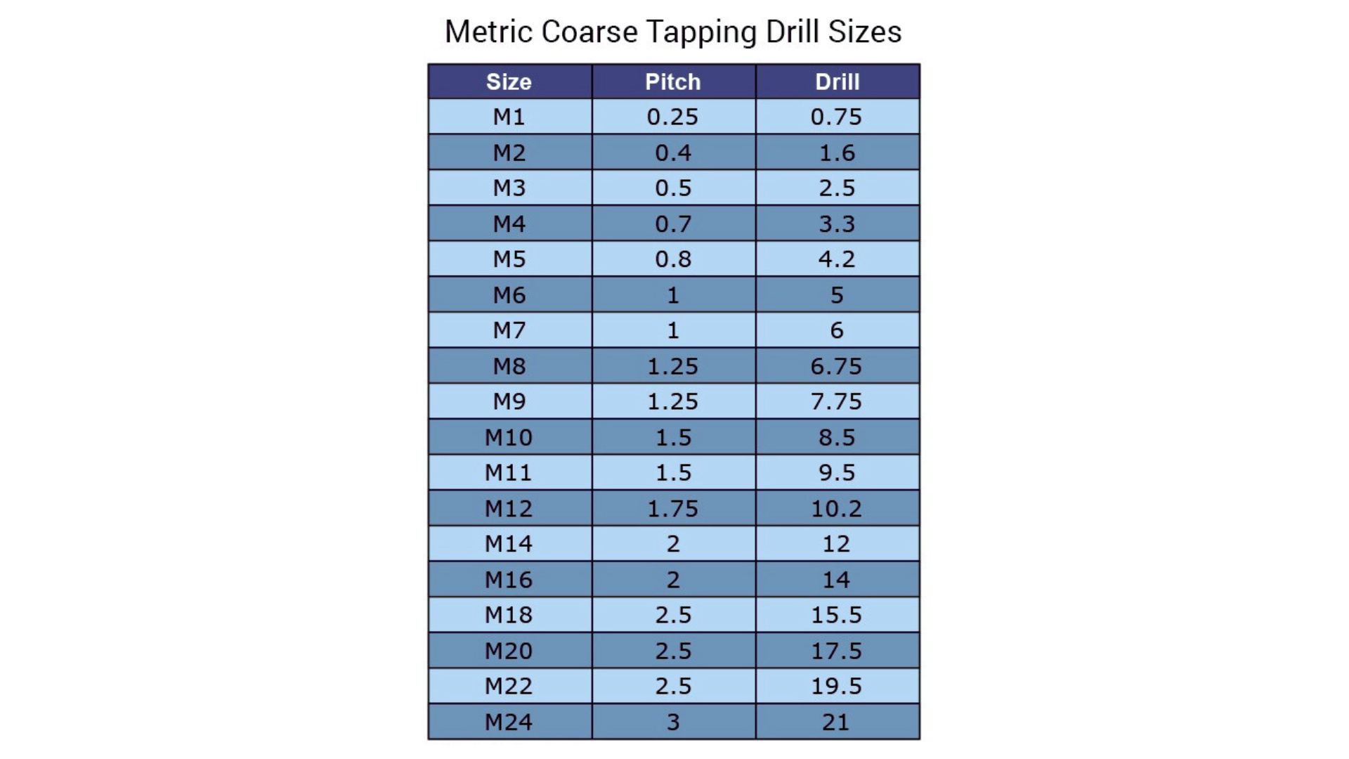
Tap Drill Chart
Image Description: A tap drill chart showing drill sizes, thread pitches, and recommended tap sizes for various threading applications.
The table gives you the corresponding drill sizes for both Coarse and Fine thread types across various standard thread sizes.
| Thread Size | Coarse Thread Drill Size | Fine Thread Drill Size |
| 1-64 | .0595 (No. 53) | .0469 (3/64) |
| 2-56 | .0700 (No. 50) | .0595 (No. 53) |
| 3-48 | .0785 (No. 47) | .0700 (No. 50) |
| 4-40 | .0890 (No. 43) | .0820 (No. 45) |
| 5-40 | .1015 (No. 38) | .0935 (No. 42) |
| 6-32 | .1065 (No. 36) | .1040 (No. 37) |
| 8-32 | .1360 (No. 29) | .1130 (No. 33) |
| 10-24 | .1495 (No. 25) | .1360 (No. 29) |
| 12-24 | .1770 (No. 16) | .1590 (No. 21) |
| 1/4-20 | .2010 (No. 7) | .1820 (No. 14) |
| 5/16-18 | .2570 (‘F’) | .2130 (No. 3) |
| 3/8-16 | .3125 (5/16) | .2720 (‘I’) |
| 7/16-14 | .3680 (‘U’) | .3320 (‘Q’) |
| 1/2-13 | .4219 (27/64) | .3906 (25/64) |
| 9/16-12 | .4844 (31/64) | .4531 (29/64) |
| 5/8-11 | .5312 (17/32) | .5156 (33/64) |
| 3/4-10 | .6562 (21/32) | .5781 (37/64) |
| 7/8-9 | .7656 (49/64) | .6875 (11/16) |
| 1″-8 | .8750 (7/8) | .8125 (13/16) |
| .9375 (59/64) |
Different Types of Threads
The most common types of threads include
Metric or International Threads
Metric (International) Threads are global thread classes. These threads are currently described by ISO (International Organization for Standardization). They are generally specified by two key dimensions:
- Pitch: The amount of space between the threads (measured in millimeters).
- Major Diameter: The number of threads per unit length in inches; it is the outer diameter of the threaded fastener in millimeters.
Some common metric thread series include: ISO Metric (M), for instance M6, M8, M10, where “M” stands for metric and the figure for the major diameter. For example, M10 x 1.5 means a 10 mm diameter of the thread major and a 1.5 mm diameter of the thread pitch, respectively.
Standard Metric Thread Tap Drill Size Chart
| Thread Size | Major Diameter (mm) | Pitch (mm) | Tap Drill Size (mm) |
| M3 | 3.0 | 0.5 | 2.5 |
| M4 | 4.0 | 0.7 | 3.3 |
| M5 | 5.0 | 0.8 | 4.2 |
| M6 | 6.0 | 1.0 | 5.0 |
| M8 | 8.0 | 1.25 | 6.8 |
| M10 | 10.0 | 1.5 | 8.5 |
| M12 | 12.0 | 1.75 | 10.2 |
| M14 | 14.0 | 2.0 | 11.8 |
| M16 | 16.0 | 2.0 | 13.0 |
| M18 | 18.0 | 2.5 | 15.0 |
| M20 | 20.0 | 2.5 | 16.5 |
| M22 | 22.0 | 2.5 | 18.5 |
| M24 | 24.0 | 3.0 | 19.5 |
| M27 | 27.0 | 3.0 | 22.0 |
| M30 | 30.0 | 3.5 | 24.5 |
| M33 | 33.0 | 3.5 | 26.5 |
Right-Hand Threads
In the right-hand thread, the fastener screws in clockwise and unscrews when anti-clockwise. Design engineers normally use these as ordinary screws, bolts, and nuts, unless they are specially designed for a particular use.
Furthermore, right-hand threads are directionally standardized to fit all applications and easily integrate with both manual and automatic operations.
Right-Hand Thread Tap Drill Size Chart
| Thread Size | Major Diameter (inches) | Pitch (inches) | Tap Drill Size (inches) |
| 1/4-20 | 0.2500 | 0.0500 | 0.2010 |
| 5/16-18 | 0.3125 | 0.0550 | 0.2570 |
| 3/8-16 | 0.3750 | 0.0625 | 0.3125 |
| 7/16-14 | 0.4375 | 0.0714 | 0.3680 |
| 1/2-13 | 0.5000 | 0.0769 | 0.4219 |
| 9/16-12 | 0.5625 | 0.0833 | 0.4844 |
| 5/8-11 | 0.6250 | 0.0909 | 0.5312 |
| 3/4-10 | 0.7500 | 0.1000 | 0.6562 |
| 7/8-9 | 0.8750 | 0.1111 | 0.7656 |
| 1″-8 | 1.0000 | 0.1250 | 0.8750 |
Left Hand Threads
Left-hand(LH) threads are used for reverse turning moments. These are tightened by a clockwise turn of a fastener and loosened by an anti-clockwise turn. The rotation applied to the bolt can loosen a normal right-hand thread in these situations. The common uses of left-hand threads include: rotating machinery, automobile wheel nuts, some valve fittings, and bicycles that need reverse rotation to undo.
Left-Hand Thread Dimensions and Tolerance Table — Inch
| Thread Size | Shoulder Diameter (Min. to Max) | Head Diameter | Head Height | Drive Size | Head Appearance |
| 1/8 | .121 to .123 | 1/4 | 1/8 | 5/64 | Knurl Only (Screws produced before 2/1/2021 may have finger grip AMPG Mark only) |
| 5/32 | .152 to .154 | 9/32 | 1/8 | 3/32 | Head Mark and Knurl |
| 3/16 | .183 to .185 | 5/16 | 5/32 | 3/32 | Head Mark and Knurl |
| 1/4 | .246 to .248 | 3/8 | 3/16 | 1/8 | Head Mark and Knurl |
| 5/16 | .308 to .310 | 7/16 | 7/32 | 5/32 | Head Mark and Knurl |
| 3/8 | .371 to .373 | 9/16 | 1/4 | 3/16 | Head Mark and Knurl |
| 1/2 | .496 to .498 | 3/4 | 5/16 | 1/4 | Head Mark and Knurl |
Taper Threads
Taper Threads entail a tapering form or conical threads that typically reduce in size. They form very compact and water-tight seals when tightened.
These threads are usually applied in NPT (National Pipe Tapered) threads. It creates an interlocking seal that prevents the passage of pressure. Moreover, taper threads are employed in plumbing, hydraulic, and pneumatic applications. Correct torque will guarantee that the seal is tight without any damage.
Tapered Pipe Threads (NPT) Dimensions and Engagement for Standard Sizes
| Nominal Size | Outside Diameter (D) | Threads per Inch (n) | Pitch of Thread (P) | Pitch Dia at the Beginning of External Thread (E0) | Hand tight Engagement Length L1 | Diameter E1 | Hand tight Engagement Length L2 | Diameter E2 |
| 1/16 | 0.3125 | 27 | 0.0370 | 0.27118 | 0.160 | 0.28118 | 0.2611 | 0.28750 |
| 1/8 | 0.405 | 27 | 0.0370 | 0.36351 | 0.1615 | 0.37360 | 0.2639 | 0.38000 |
| 1/4 | 0.540 | 18 | 0.0555 | 0.47739 | 0.2278 | 0.49163 | 0.4018 | 0.50250 |
| 3/8 | 0.675 | 18 | 0.0555 | 0.61201 | 0.240 | 0.62701 | 0.4078 | 0.63750 |
| 1/2 | 0.840 | 14 | 0.0714 | 0.75843 | 0.320 | 0.77843 | 0.5337 | 0.79179 |
| 3/4 | 1.050 | 14 | 0.0714 | 0.96768 | 0.339 | 0.98887 | 0.5457 | 1.00179 |
| 1 | 1.315 | 11.5 | 0.0869 | 1.21363 | 0.400 | 1.23863 | 0.6828 | 1.25630 |
| 1-1/4 | 1.660 | 11.5 | 0.0869 | 1.55713 | 0.420 | 1.58338 | 0.7068 | 1.60130 |
| 1-1/2 | 1.900 | 11.5 | 0.0869 | 1.79609 | 0.420 | 1.82234 | 0.7235 | 1.84130 |
| 2 | 2.375 | 11.5 | 0.0869 | 2.26902 | 0.436 | 2.29627 | 0.7565 | 2.31630 |
| 2-1/2 | 2.875 | 8 | 0.1250 | 2.71953 | 0.682 | 2.76216 | 1.1375 | 2.79062 |
| 3 | 3.5 | 8 | 0.1250 | 3.34062 | 0.766 | 3.38850 | 1.2000 | 3.41562 |
| 3-1/2 | 4.0 | 8 | 0.1250 | 3.83750 | 0.821 | 3.88881 | 1.2500 | 3.91562 |
| 4 | 4.5 | 8 | 0.1250 | 4.33438 | 0.844 | 4.38712 | 1.3000 | 4.41562 |
| 5 | 5.563 | 8 | 0.1250 | 5.39073 | 0.937 | 5.44929 | 1.4063 | 5.47862 |
| 6 | 6.625 | 8 | 0.1250 | 6.44609 | 0.958 | 6.50597 | 1.5125 | 6.54062 |
| 8 | 8.625 | 8 | 0.1250 | 8.43359 | 1.063 | 8.50003 | 1.7125 | 8.54062 |
| 10 | 10.750 | 8 | 0.1250 | 10.54531 | 1.210 | 10.62094 | 1.9250 | 10.66562 |
| 12 | 12.750 | 8 | 0.1250 | 12.53281 | 1.360 | 12.61781 | 2.1250 | 12.66562 |
V-Shaped Threads
V-shaped threads keep an angled cross-sectional shape with angles from 30 to 60 degrees.
These threads are designed by engineers to offer appreciable mechanical interconnects. In addition to their application, they are mainly used in bolts, screws, and other fasteners. Their shape enables the load to be spread evenly along the entire length of the thread, and across the width as well. High torque is best served with V-shaped threads.
British Standard Threads
British Standard Threads (BST) is a group of thread forms mainly used in Britain and other countries of the Commonwealth.
BSW threads are of 55° thread angle. In addition, BSF threads confine finer pitches for use in more accurate purposes. Industries like machinery, automotive, and engineering use these threads for secure joining purposes.
G/BSP Thread Type – British Standard Pipe (BSPT)
| Dash Size (Nominal Size) | Thread Pitch | Male Thread O.D. (mm) | Male Thread O.D. (inches) | Female Thread I.D. (mm) | Female Thread I.D. (inches) |
| -02 (1/8) | 28 | 9.7 | 0.38 | 8.9 | 0.35 |
| -04 (1/4) | 19 | 13.2 | 0.52 | 11.9 | 0.47 |
| -06 (3/8) | 19 | 16.5 | 0.65 | 15.2 | 0.60 |
| -08 (1/2) | 14 | 20.8 | 0.82 | 19.1 | 0.75 |
| -10 (5/8) | 14 | 22.4 | 0.88 | 20.3 | 0.80 |
| -12 (3/4) | 14 | 26.4 | 1.04 | 24.6 | 0.97 |
| -16 (1) | 11 | 33.0 | 1.30 | 31.0 | 1.22 |
| -20 (1 ¼) | 11 | 41.9 | 1.65 | 39.6 | 1.56 |
| -24 (1 ½) | 11 | 47.8 | 1.88 | 45.5 | 1.79 |
| -32 (2) | 11 | 59.7 | 2.35 | 57.4 | 2.26 |
Seller Threads
Seller threads suit sealing pipe fittings well. These threads taper and fit tightly when tightened to the correct standard.
Seller threads are used in hydraulic and pneumatic applications to prevent leakage. Moreover, their form is helpful; to avoid loosening because of vibrations or pressure fluctuations.
Square Threads
Square Threads are flat and square-shaped threads with 90 degrees included angle. They provide excellent load-carrying capability and power transfer.
In addition, manufacturers use square threads in lead screws and mechanical drives. Because these threads reduce sliding and can endure high-pressure loads.
Square Thread Dimensions According to ISO Standards
| Nominal Diameter (mm) | Pitch (mm) | Example Thread Type | Thread Configuration |
| 22, 24, 26, 28 | 5 | Sq 60×5 | Single Start |
| 30, 32, 36 | 6 | Sq 60×6 | Single Start |
| 40, 44 | 7 | Sq 60×7 | Single Start |
| 48, 50, 52 | 8 | Sq 60×8 | Single Start |
| 55, 60 | 9 | Sq 60×9 | Single Start |
| 65, 70, 75, 80 | 10 | Sq 60×10 | Single Start |
| 85, 90, 95, 100 | 12 | Sq 60×12 | Single Start |
| Example with Lead | Sq 60×18(P9)LH | Two Start, Left Hand |
ACME Threads
The ACME Threads contain a trapezoidal profile with an angle of 29 degrees. They offer a perfect proposition between power and performance. Engineers, ACME threads use in lead screws and linear actuators.
Since these threads have more space below and above the waves. Furthermore, they give more load-carrying capacity and minimize friction than square threads.
Acme Thread Designation and Dimensions
| Designation | TPI | Tolerance Class | Major Dia. (in) | Pitch Dia. (in) | Minor Dia. (in) |
| 1/4-16 Acme | 16 | 2G | 0.2500 | 0.2450 | 0.1775 |
| 1/4-16 Acme | 16 | 3G | 0.2500 | 0.2450 | 0.1775 |
| 5/16-14 Acme | 14 | 2G | 0.3125 | 0.3075 | 0.2311 |
| 5/16-14 Acme | 14 | 3G | 0.3125 | 0.3075 | 0.2311 |
| 3/8-12 Acme | 12 | 2G | 0.3750 | 0.3700 | 0.2817 |
| 3/8-12 Acme | 12 | 3G | 0.3750 | 0.3700 | 0.2817 |
| 1/2-10 Acme | 10 | 2G | 0.5000 | 0.4950 | 0.3800 |
| 1/2-10 Acme | 10 | 3G | 0.5000 | 0.4950 | 0.3800 |
| 5/8-8 Acme | 8 | 2G | 0.6250 | 0.6188 | 0.4800 |
| 5/8-8 Acme | 8 | 3G | 0.6250 | 0.6188 | 0.4800 |
| 3/4-6 Acme | 6 | 2G | 0.7500 | 0.7417 | 0.5633 |
| 3/4-6 Acme | 6 | 3G | 0.7500 | 0.7417 | 0.5633 |
| 1-5 Acme | 5 | 2G | 1.0000 | 0.9900 | 0.7800 |
| 1-5 Acme | 5 | 3G | 1.0000 | 0.9900 | 0.7800 |
| 1 1/4-5 Acme | 5 | 2G | 1.2500 | 1.2400 | 1.0300 |
| 1 1/4-5 Acme | 5 | 3G | 1.2500 | 1.2400 | 1.0300 |
| 2-4 Acme | 4 | 2G | 2.0000 | 1.9875 | 1.7300 |
| 2-4 Acme | 4 | 3G | 2.0000 | 1.9875 | 1.7300 |
| 3-2 Acme | 2 | 2G | 3.0000 | 2.9750 | 2.4800 |
| 3-2 Acme | 2 | 3G | 3.0000 | 2.9750 | 2.4800 |
| 4-2 Acme | 2 | 2G | 4.0000 | 3.9750 | 3.4800 |
| 4-2 Acme | 2 | 3G | 4.0000 | 3.9750 | 3.4800 |
Knuckle Threads
Knuckle Threads are convex form threads similar to the human knuckle. You can drill these threads for lids, caps, and hand tools. In addition, the rounded design of the threads works to reduce the possibility of cross-threading and guarantees a better fit.
Table: Knuckle TPI (Threads per Inch), pitch, and the various diameters (major, pitch, and minor) with their respective maximum and minimum values.
| Thread Designation | TPI | Pitch (mm) | Major Diameter (mm) | Pitch Diameter (mm) | Minor Diameter (mm) | Max (mm) | Min (mm) | Max (mm) |
| Rd 8 x 1/10 | 10 | 2.540 | 8.000 | 7.665 | 6.730 | 6.530 | 5.460 | 5.210 |
| Rd 9 x 1/10 | 10 | 2.540 | 9.000 | 8.665 | 7.730 | 7.530 | 6.460 | 6.210 |
| Rd 10 x 1/10 | 10 | 2.540 | 10.000 | 9.665 | 8.730 | 8.530 | 7.460 | 7.210 |
| Rd 11 x 1/10 | 10 | 2.540 | 11.000 | 10.665 | 9.730 | 9.530 | 8.460 | 8.210 |
| Rd 12 x 1/10 | 10 | 2.540 | 12.000 | 11.665 | 10.730 | 10.530 | 9.460 | 9.210 |
| Rd 14 x 1/8 | 8 | 3.175 | 14.000 | 13.625 | 12.730 | 12.494 | 10.825 | 10.525 |
| Rd 16 x 1/8 | 8 | 3.175 | 16.000 | 15.625 | 14.412 | 14.176 | 12.825 | 12.525 |
| Rd 18 x 1/8 | 8 | 3.175 | 18.000 | 17.625 | 16.412 | 16.176 | 14.825 | 14.525 |
| Rd 20 x 1/8 | 8 | 3.175 | 20.000 | 19.625 | 18.412 | 18.176 | 16.825 | 16.525 |
| Rd 22 x 1/8 | 8 | 3.175 | 22.000 | 21.625 | 20.412 | 20.176 | 18.825 | 18.525 |
| Rd 24 x 1/8 | 8 | 3.175 | 24.000 | 23.625 | 22.412 | 22.176 | 20.825 | 20.525 |
| Rd 26 x 1/8 | 8 | 3.175 | 26.000 | 25.625 | 24.412 | 24.176 | 22.825 | 22.525 |
| Rd 28 x 1/8 | 8 | 3.175 | 28.000 | 27.625 | 26.412 | 26.176 | 25.825 | 25.525 |
| Rd 30 x 1/8 | 8 | 3.175 | 30.000 | 29.625 | 28.412 | 28.176 | 26.825 | 26.525 |
| Rd 32 x 1/8 | 8 | 3.175 | 32.000 | 31.625 | 30.412 | 30.176 | 28.825 | 28.525 |
| Rd 34 x 1/8 | 8 | 3.175 | 34.000 | 33.625 | 32.412 | 32.176 | 30.825 | 30.525 |
| Rd 36 x 1/8 | 8 | 3.175 | 36.000 | 35.625 | 34.412 | 34.176 | 32.825 | 32.525 |
| Rd 38 x 1/8 | 8 | 3.175 | 38.000 | 37.625 | 36.412 | 36.176 | 34.825 | 34.525 |
| Rd 40 x 1/6 | 6 | 4.233 | 40.000 | 39.525 | 37.883 | 37.583 | 35.767 | 35.392 |
| Rd 42 x 1/6 | 6 | 4.233 | 42.000 | 41.525 | 39.883 | 39.583 | 37.767 | 37.392 |
| Rd 44 x 1/6 | 6 | 4.233 | 44.000 | 43.525 | 41.883 | 41.583 | 39.767 | 39.392 |
| Rd 46 x 1/6 | 6 | 4.233 | 46.000 | 45.525 | 43.883 | 43.583 | 41.767 | 41.392 |
| Rd 48 x 1/6 | 6 | 4.233 | 48.000 | 47.525 | 45.883 | 45.583 | 43.767 | 43.392 |
| Rd 50 x 1/6 | 6 | 4.233 | 50.000 | 49.525 | 47.883 | 47.583 | 45.767 | 45.392 |
| Rd 52 x 1/6 | 6 | 4.233 | 52.000 | 51.525 | 49.883 | 49.583 | 47.767 | 47.392 |
| Rd 55 x 1/6 | 6 | 4.233 | 55.000 | 54.525 | 52.883 | 52.583 | 50.767 | 50.392 |
| Rd 58 x 1/6 | 6 | 4.233 | 58.000 | 57.525 | 55.883 | 55.583 | 53.767 | 53.392 |
| Rd 60 x 1/6 | 6 | 4.233 | 60.000 | 59.525 | 57.883 | 57.583 | 55.767 | 55.392 |
| Rd 62 x 1/6 | 6 | 4.233 | 62.000 | 61.525 | 59.883 | 59.583 | 57.767 | 57.392 |
| Rd 65 x 1/6 | 6 | 4.233 | 65.000 | 64.525 | 62.883 | 62.583 | 60.767 | 60.392 |
| Rd 68 x 1/6 | 6 | 4.233 | 68.000 | 67.525 | 65.883 | 65.583 | 63.767 | 63.392 |
| Rd 70 x 1/6 | 6 | 4.233 |
Buttress Threads
Buttress Threads comprise an asymmetrical shape. These threads have a steep flank and a shallow flank. They intend to carry axial loads in one direction. Power transmission systems use buttress threads and place them in jacks and heavy equipment.
Butter Thread Standard Chart
| Thread | Pitch diameter (mm) | Outer diameter – internal thread (mm) | Core diameter – External Thread (mm) | Core diameter – Internal Thread (mm) |
| S10x2 | 8.5 | 10 | 6.529 | 7 |
| S12x2 | 10.5 | 12 | 8.529 | 9 |
| S12x3 | 9.75 | 12 | 6.793 | 7.5 |
| S14x2 | 12.5 | 14 | 10.529 | 11 |
| S14x3 | 11.75 | 14 | 8.793 | 9.5 |
| S16x2 | 14.5 | 16 | 12.529 | 13 |
| S16x4 | 13 | 16 | 9.058 | 10 |
| S18x2 | 16.5 | 18 | 14.529 | 15 |
| S18x4 | 15 | 18 | 11.058 | 12 |
| S20x2 | 18.5 | 20 | 16.529 | 17 |
| S20x4 | 17 | 20 | 13.058 | 14 |
| S22x3 | 19.75 | 22 | 16.793 | 17.5 |
| S22x5 | 18.25 | 22 | 13.322 | 14.5 |
| S22x8 | 16 | 22 | 8.116 | 10 |
| S24x3 | 21.75 | 24 | 18.793 | 19.5 |
| S24x5 | 20.25 | 24 | 15.322 | 16.5 |
| S24x8 | 18 | 24 | 10.116 | 12 |
| S26x3 | 23.75 | 26 | 20.793 | 21.5 |
| S26x5 | 22.25 | 26 | 17.322 | 18.5 |
| S26x8 | 20 | 26 | 12.116 | 14 |
| S28x3 | 25.75 | 28 | 22.793 | 23.5 |
| S28x5 | 24.25 | 28 | 19.322 | 20.5 |
| S28x8 | 22 | 28 | 14.116 | 16 |
| S30x3 | 27.75 | 30 | 24.793 | 25.5 |
| S30x6 | 25.5 | 30 | 19.587 | 21 |
| S30x10 | 22.5 | 30 | 12.645 | 15 |
| S32x3 | 29.75 | 32 | 26.793 | 27.5 |
| S32x6 | 27.5 | 32 | 21.587 | 23 |
| S32x10 | 24.5 | 32 | 14.645 | 17 |
| S34x3 | 31.75 | 34 | 28.793 | 29.5 |
| S34x6 | 29.5 | 34 | 23.587 | 25 |
| S34x10 | 26.5 | 34 | 16.645 | 19 |
| S36x3 | 33.75 | 36 | 30.793 | 31.5 |
| S36x6 | 31.5 | 36 | 25.587 | 27 |
| S36x10 | 28.5 | 36 | 18.645 | 21 |
| S38x3 | 35.75 | 38 | 32.793 | 33.5 |
| S38x7 | 32.75 | 38 | 25.851 | 27.5 |
| S38x10 | 30.5 | 38 | 20.645 | 23 |
| S40x3 | 37.75 | 40 | 34.793 | 35.5 |
| S40x7 | 34.75 | 40 | 27.851 | 29.5 |
| S40x10 | 32.5 | 40 | 22.645 | 25 |
| S42x3 | 39.75 | 42 | 36.793 | 37.5 |
| S42x7 | 36.75 | 42 | 29.851 | 31.5 |
| S42x10 | 34.5 | 42 | 24.645 | 27 |
| S44x3 | 41.75 | 44 | 38.793 | 39.5 |
| S44x7 | 38.75 | 44 | 31.851 | 33.5 |
| S44x12 | 35 | 44 | 23.174 | 26 |
| S46x3 | 43.75 | 46 | 40.793 | 41.5 |
| S46x8 | 40 | 46 | 32.116 | 34 |
| S46x12 | 37 | 46 | 25.174 | 28 |
| S48x3 | 45.75 | 48 | 42.793 | 43.5 |
| S48x8 | 42 | 48 | 34.116 | 36 |
| S48x12 | 39 | 48 | 27.174 | 30 |
| S50x3 | 47.75 | 50 | 44.793 | 45.5 |
| S50x8 | 44 | 50 | 36.116 | 38 |
| S50x12 | 41 | 50 | 29.174 | 32 |
| S52x3 | 49.75 | 52 | 46.793 | 47.5 |
| S52x8 | 46 | 52 | 38.116 | 40 |
| S52x12 | 43 | 52 | 31.174 | 34 |
| S55x3 | 52.75 | 55 | 49.793 | 50.5 |
| S55x9 | 48.25 | 55 | 39.38 | 41.5 |
| S55x14 | 44.5 | 55 | 30.702 | 34 |
| S60x3 | 57.75 | 60 | 54.793 | 55.5 |
| S60x9 | 53.25 | 60 | 44.38 | 46.5 |
| S60x14 | 49.5 | 60 | 35.702 | 39 |
| S65x4 | 62 | 65 | 58.058 | 59 |
| S65x10 | 57.5 | 65 | 47.645 | 50 |
| S65x16 | 53 | 65 | 37.231 | 41 |
| S70x4 | 67 | 70 | 63.058 | 64 |
| S70x10 | 62.5 | 70 | 52.645 | 55 |
| S70x16 | 58 | 70 | 42.231 | 46 |
| S75x4 | 72 | 75 | 68.058 | 69 |
| S75x10 | 67.5 | 75 | 57.645 | 60 |
| S75x16 | 63 | 75 | 47.231 | 51 |
| S80x4 | 77 | 80 | 73.058 | 74 |
| S80x10 | 72.5 | 80 | 62.645 | 65 |
| S80x16 | 68 | 80 | 52.231 | 56 |
| S85x4 | 82 | 85 | 78.058 | 79 |
| S85x12 | 76 | 85 | 64.174 | 67 |
| S85x18 | 71.5 | 85 | 53.76 | 58 |
| S90x4 | 87 | 90 | 83.058 | 84 |
| S90x12 | 81 | 90 | 69.174 | 72 |
| S90x18 | 76.5 | 90 | 58.76 | 63 |
| S95x4 | 92 | 95 | 88.058 | 89 |
| S95x12 | 86 | 95 | 74.174 | 77 |
| S95x18 | 81.5 | 95 | 63.76 | 68 |
| S100x4 | 97 | 100 | 93.058 | 94 |
| S100x12 | 91 | 100 | 79.174 | 82 |
| S100x20 | 85 | 100 | 65.289 | 70 |
| S105x4 | 102 | 105 | 98.058 | 99 |
| S105x12 | 96 | 105 | 84.174 | 87 |
| S105x20 | 90 | 105 | 70.289 | 75 |
| S110x4 | 107 | 110 | 103.058 | 104 |
| S110x12 | 101 | 110 | 89.174 | 92 |
| S110x20 | 95 | 110 | 75.289 | 80 |
| S115x6 | 110.5 | 115 | 104.587 | 106 |
| S115x14 | 104.5 | 115 | 90.702 | 94 |
| S115x22 | 98.5 | 115 | 76.818 | 82 |
| S120x6 | 115.5 | 120 | 109.587 | 111 |
| S120x14 | 109.5 | 120 | 95.702 | 99 |
| S120x22 | 103.5 | 120 | 81.818 | 87 |
| S125x6 | 120.5 | 125 | 114.587 | 116 |
| S125x14 | 114.5 | 125 | 100.702 | 104 |
| S125x22 | 108.5 | 125 | 86.818 | 92 |
| S130x6 | 125.5 | 130 | 119.587 | 121 |
| S130x14 | 119.5 | 130 | 105.702 | 109 |
| S130x22 | 113.5 | 130 | 91.818 | 97 |
Worm Threads
Designers intend worm threads to be spiral in shape, similar to a screw. They frequently apply them in worm gears to reduce torque and increase mechanical advantage. Therefore, applications that need high reduction ratios and compact structures benefit most from these threads.
Worm Thread Profiles with Pitch Diameters, Diametral Pitch, and Other Specifications
| Row | Typical Pitch Diameter (inches) | Diametral Pitch (DP) | Pitch (n/DP) | Addendum (1/DP) | Whole Depth (Pitch x 0.686) | Worm Thread Profile |
| 1 | 3.000 | 4 | 0.7854 | 0.2500 | 0.5388 | Worm Thread Profile – 3.000 |
| 2 | 2.500 | 5 | 0.6283 | 0.2000 | 0.4310 | Worm Thread Profile – 2.500 |
| 3 | 2.000 | 6 | 0.5236 | 0.1667 | 0.3592 | Worm Thread Profile – 2.000 |
| 4 | 1.750 | 7 | 0.4488 | 0.1429 | 0.3079 | Worm Thread Profile – 1.750 |
| 5 | 1.500 | 8 | 0.3927 | 0.1250 | 0.2694 | Worm Thread Profile – 1.500 |
| 6 | 1.375 | 9 | 0.3491 | 0.1111 | 0.2395 | Worm Thread Profile – 1.375 |
| 7 | 1.250 | 10 | 0.3142 | 0.1000 | 0.2155 | Worm Thread Profile – 1.250 |
| 8 | 1.125 | 11 | 0.2856 | 0.0909 | 0.1959 | Worm Thread Profile – 1.125 |
| 9 | 1.000 | 12 | 0.2618 | 0.0833 | 0.1796 | Worm Thread Profile – 1.000 |
| 10 | 0.813 | 14 | 0.2244 | 0.0714 | 0.1539 | Worm Thread Profile – 0.813 |
| 11 | 0.625 | 16 | 0.1963 | 0.0625 | 0.1347 | Worm Thread Profile – 0.625 |
| 12 | 0.583 | 18 | 0.1745 | 0.0556 | 0.1197 | Worm Thread Profile – 0.583 |
| 13 | 0.542 | 20 | 0.1571 | 0.0500 | 0.1078 | Worm Thread Profile – 0.542 |
| 14 | 0.500 | 24 | 0.1309 | 0.0417 | 0.0898 | Worm Thread Profile – 0.500 |
| 15 | 0.469 | 28 | 0.1122 | 0.0357 | 0.0700 | Worm Thread Profile – 0.469 |
| 16 | 0.438 | 32 | 0.0982 | 0.0313 | 0.0673 | Worm Thread Profile – 0.438 |
| 17 | 0.407 | 40 | 0.0785 | 0.0250 | 0.0539 | Worm Thread Profile – 0.407 |
| 18 | 0.375 | 48 | 0.0654 | 0.0208 | 0.0449 | Worm Thread Profile – 0.375 |
Single & Multi Threads
Single Threads have only one line of thread along the entire fastener length.
Engineers mainly apply them to normal bolts, screws, and other fasteners used in the construction industry.
Multiple Threads, on the other hand, multiple threads include several threads along the same length. They expand the engagement area and enable faster threading. You can use multi-threads in high-speed or high-load applications where assembly time is a major concern.
Standard Design Table for Single & Multi Threads
| Thread Type | Nominal Diameter (mm) | Pitch (mm) | Threads per Inch (TPI) | Core Diameter (External Thread) | Core Diameter (Internal Thread) | Major Diameter (External Thread) | Pitch Diameter (Internal Thread) | Thread Depth (mm) | Thread Profile |
| Single Thread | 5.0 | 0.8 | 32 | 4.2 | 4.8 | 5.0 | 4.6 | 0.4 | ISO 68° |
| Single Thread | 8.0 | 1.0 | 25 | 6.9 | 7.1 | 8.0 | 7.6 | 0.5 | ISO 60° |
| Single Thread | 10.0 | 1.5 | 20 | 8.5 | 9.0 | 10.0 | 9.7 | 0.6 | ISO 60° |
| Single Thread | 12.0 | 1.75 | 18 | 10.1 | 10.6 | 12.0 | 11.5 | 0.7 | ISO 60° |
| Multi Thread | 8.0 | 1.25 | 24 | 6.5 | 6.9 | 8.0 | 7.8 | 0.45 | ISO 60° |
| Multi Thread | 12.0 | 2.0 | 15 | 10.8 | 11.3 | 12.0 | 11.9 | 0.8 | ISO 60° |
| Multi Thread | 15.0 | 2.5 | 12 | 13.5 | 14.0 | 15.0 | 14.8 | 1.0 | ISO 60° |
| Multi Thread | 20.0 | 3.0 | 10 | 18.0 | 18.6 | 20.0 | 19.8 | 1.2 | ISO 60° |
| Multi Thread | 25.0 | 3.5 | 8 | 22.3 | 22.9 | 25.0 | 24.8 | 1.5 | ISO 60° |
| Multi Thread | 30.0 | 4.0 | 6 | 27.4 | 28.1 | 30.0 | 29.8 | 1.8 | ISO 60° |
Material Strength and Hardness Properties for Threading and Drilling
| Material | Specification | Tensile Strength (psi) | Yield Strength (psi) | Shear Strength (psi) | Elongation | Brinell Hardness (BHN) | Rockwell Hardness |
| Aluminum 6061-T6 | ASTM B211 | 45,000 | 40,000 | 22,500 | 17% | BHN 95 | B56 |
| Brass 360 | ASTM B16 | 58,000 | 45,000 | 29,000 | 25% | BHN 143 | B78 |
| Nickel Alloy 405 (Monel) | ASTM B164 | 85,000 | 60,000 | 42,500 | 24% | BHN 163 | B85 |
| Stainless Steel 18-8 (303) | ASTM A582 | 90,000 | 35,000 | 45,000 | 50% | BHN 160 | B83 |
| Stainless Steel 316 | ASTM A276 | 75,000 | 30,000 | 37,500 | 45% | BHN 160 | B83 |
| Steel 12L14 | ASTM A108 | 78,000 | 60,000 | 39,000 | 15% | BHN 160 | B84 |
| Steel Alloy C4140/41L40 | ASTM A108 Cold | 105,000 | 85,000 | 52,500 | 15% | BHN 187 | B91 |
| Steel Alloy C4140/41L40 | ASTM A108 Thru Hard | 140,000 | 105,000 | 70,000 | n/a | BHN 300 | B91 |
Considerations For Selecting The Right Type of Thread
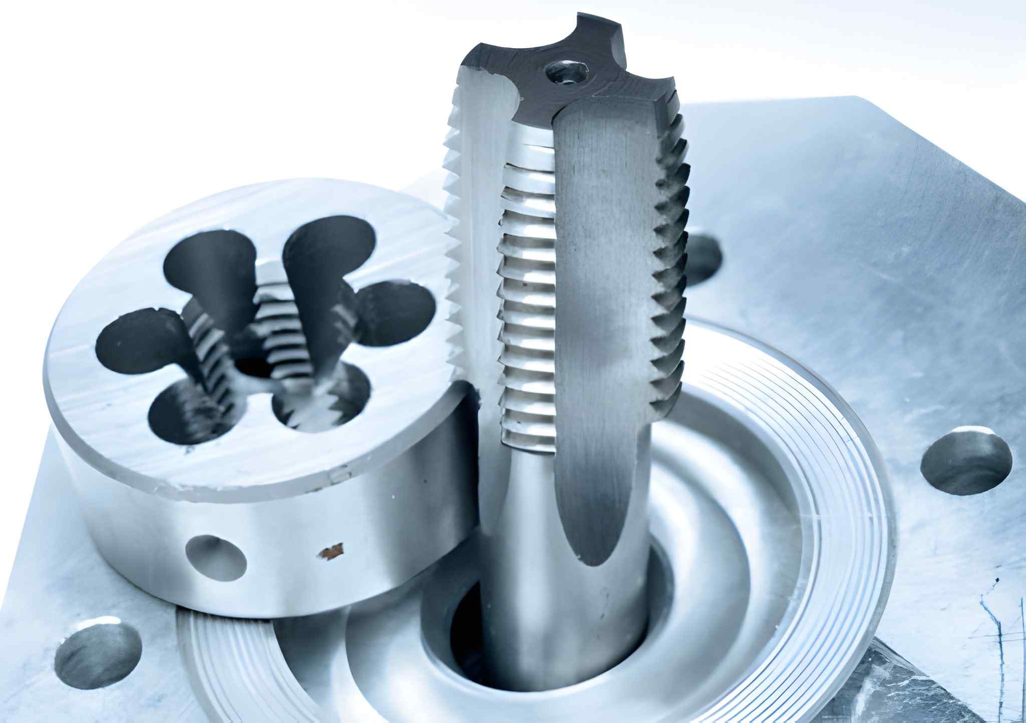
Tap and other carving details, tools, and Toning
Image Description: A detailed image showing taps, carving tools, and toning equipment used for threading and surface detailing in precision machining.
For choosing the right type, consider the following factors to make the choice easier;
- Application Requirements: Choose the thread type by considering the load, torque, and environmental conditions of the application. For instance, manufacturers utilize to accomplish leak-proof joints, and V-threads provide mechanical fastening joints.
- Material Compatibility: Soft materials may need thinner threads than hard materials, which need thick threads.
- Thread Strength: You can consider the actual load as desired. Generally, coarse threads bear higher resistance levels to stripping, and fine threads are optimal for confined areas.
- Assembly Speed: Use multi-threaded fasteners if you need quick assembly. Because they are relatively faster to engage than single-threaded.
- Durability and Wear Resistance: In cases of frequent usage, apply thread types like the ‘Acme Buttress threads’ because these types of threads can easily withstand higher loads and resist wear effectively.
Summary
To sum up, the ultimate selection of thread depends on the requirements for mechanical connections and structural aspects. Other factors to bear in micro thread design include the specific application requirements, material compatibility with interference thread, and the strength and rigor required of the threads. Taper, V-shaped, and ACME standard threads feature different benefits according to the load-carrying capability, sealing adequacy, and accuracy degree.
Moreover, the decision of whether to employ a single-threaded or multi-threaded design can make a difference of tens of seconds in the time needed to assemble. Therefore, it’s possible to select threads according to functional and operational requirements, which will guarantee their further stability and effectiveness in the long run.
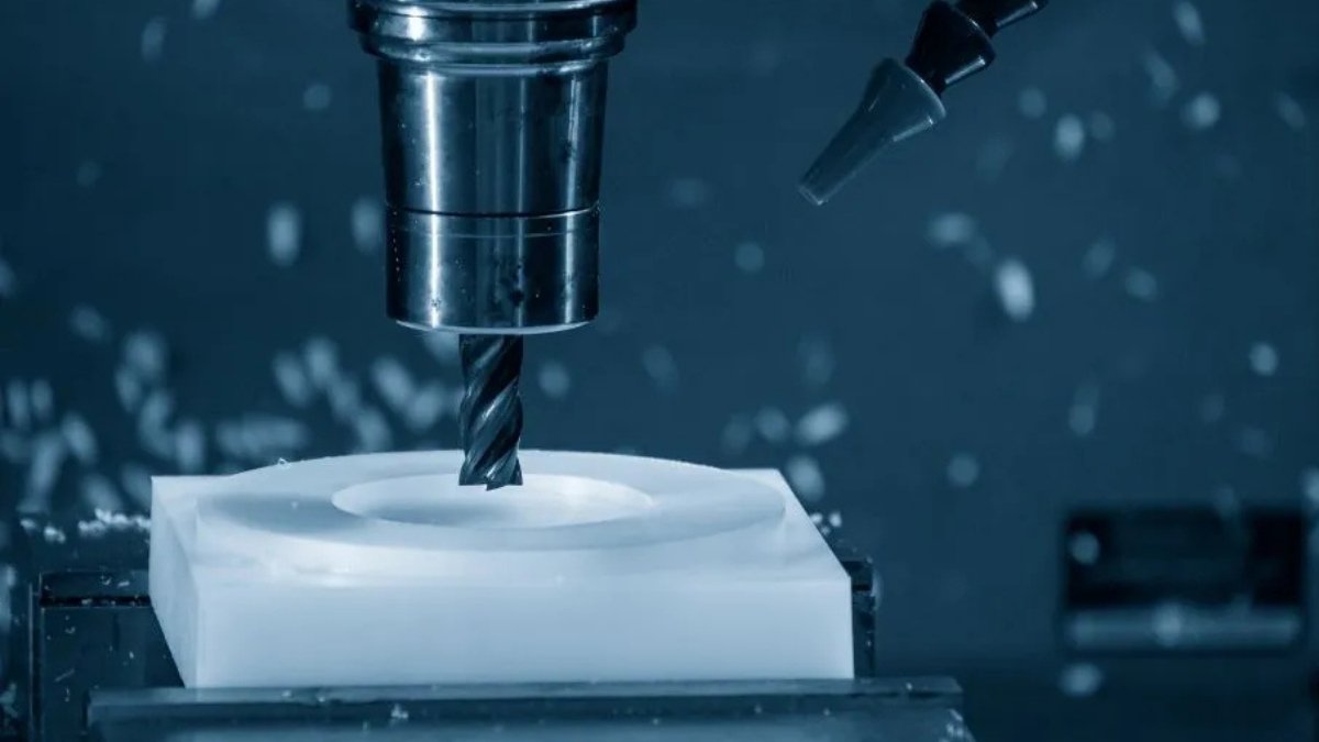
Choosing the right tap drill size is critical to ensure parts are threaded and guarantee their function. And it is same important for CNC machining.
FAQ’s
Q1. What is the difference between coarse and fine threads?
Coarse threads are wider and deeper compared to fine threads. Therefore, these threads are less likely to strip. In contrast, thin pitches also mean smaller diameter threads, with more threads to the inch, which makes for a closer fit.
Q2. How do I choose the correct tap drill size?
You can obtain the correct tap drill size by subtracting the thread pitch from the major diameter of the fastener. For instance, for an M10 x 1.5 thread, the tap drill size would be equal to M10 – 1.5 mm = 8.5 mm. Though recommended tap drill sizes vary from table to table.
Q3. What are the benefits of using taper threads?
Taper threads produce pressure-tight joints through thread wedging. Moreover, they provide leak-proof features and are notable in systems where high pressure or vibration is usual.
Q4. Why do engineers prefer ACME threads in lead screws?
ACME threads are of trapezoidal cross-sections. These threads hold fair strength, load-carrying capacity, and minimum friction. They commonly use lead screws in linear motion applications. Lead screws can sustain high axial loads. They also provide a smooth operational profile over time.


