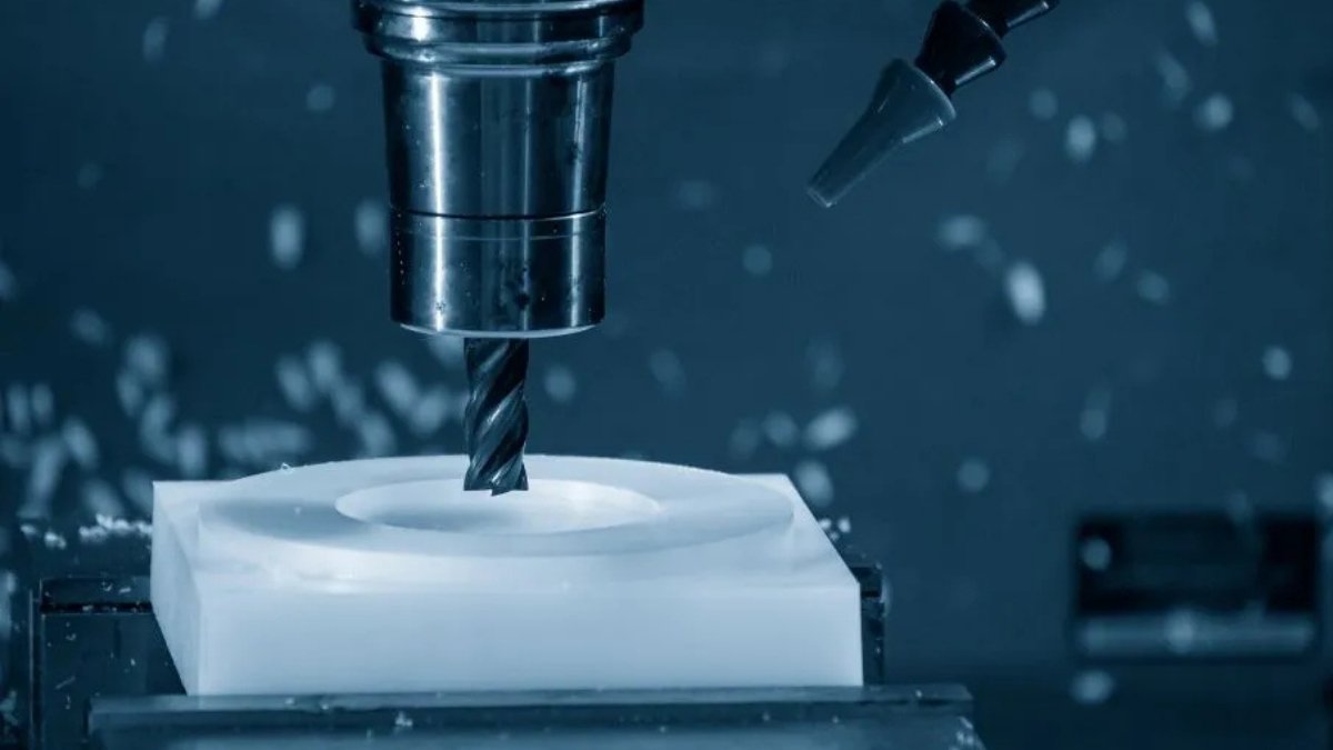
DESIGN GUIDELINES FOR CNC MACHINING
CNC machining is one of the most versatile manufacturing processes used to make parts with high precision and top quality. As efficient as the technology is, your end-part quality is just as great as the design work put into the process. CNC machines have certain design limitations that, when unconsidered, may flaw the production process, increase leadtimes, and adversely impact the cost. These design restrictions are chiefly due to the machining process itself, tool access, and tool geometry.
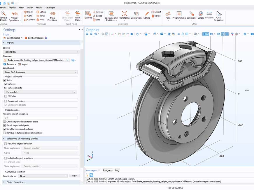
Designing for CNC machining can be improved by simply following these rules and guidelines. Our design-for-manufacturability guide can also help you trim costs, shorten leadtimes, and improve your parts’ overall quality. This paper covers various aspects of CAD designs and significant considerations for designing features for CNC machining.
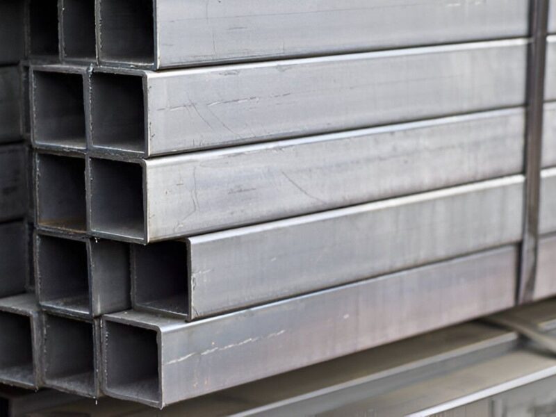
• Material consideration
When it comes to a material consideration, the speed of machining, material hardness, and finishing aesthetics are all critical in design for CNC. Softer materials like aluminum will be easier and faster to machine than steel and titanium. Aluminum is quicker to machine than steel, while titanium is tougher to cut into shape than steel. Plastic materials for instance have low cost and can be finished in a variety of ways. Your part may however, experience some level of warping after machining. Material consideration therefore remains a crucial step in design, process and leadtime optimization.
• Tolerances
Tolerances are the limits within which a deviation from the original dimension is considered acceptable. They work like the boundary for the acceptable dimension of a feature in any CNC design. Tolerances should only be used when critical to the design. When used, they should also be homogenous to reduce machining time. The standard tolerance for most machine shops is 0.05mm when unspecified. At Premium Parts, we can achieve up to ±0.005m on some specified dimensions, however, this is subject to increased cost and leadtimes. When designing, consider the tolerances around mating parts to ensure fit post-machining. Evaluate your part’s functionality in extreme cases before calculating the effect of deviation and the acceptable tolerances.
• Walls
Avoid adding thin walls into the design of your parts for CNC machining. Using moderate and standard wall sizes will improve the strength and accuracy of your CNC process. At a minimum, ensure that your plastic parts have a wall thickness of at least 1.5mm, while metal parts have at least 0.8mm. Thinner walls increase the vibrations generated during machining and lower your chances of part accuracy. Thinner walls may also become softer due to temperature changes in their applications or warp due to residual stress. Away from the standard recommendations, walls with thicknesses of 0.5mm and 1mm for plastic and metal parts are achievable. If thin walls are a must, you may consider sheet metal fabrication to ensure cost-effectiveness.

• Cavities
The depth of cavities in CNC design must be limited to four times their width. This is because cutting tools like end mills have a limit to the length that they can cut. Cavities too deep will cause tool deflection, tool hanging, tool fracture, and difficulty in chip evacuation, and using longer tools will reduce the accuracy or damage your part. Simply doubling the length of your cutting tool will increase tool deflection up to eight times.
Deep cavities will also increase the overall project cost as a lot of materials need to be removed. Shorter cutting tools with larger diameters always shorten machining times. Any cavity that is more than six times the diameter of the tool is considered deep. If you require a larger cavity depth, use a variable depth that allows for different tools.

• Inner edges / Radii
When designing inner edges, it is recommended that you add a radius. Since most of the cutting tools used during machining are cylindrical, they cannot machine sharp inner edges. The use of radii also prevents wear and tear of the tool. As a rule of thumb, use a radius that is 1.3 times the milling tool radius as your inner edge radius. For instance, when working with a milling tool with a radius of 10mm, your inner edge radius should be 13mm. The recommended vertical corner radii for inner edges is 1/3 times the cavity depth or higher. This will allows for a better quality surface finish. If you need a 90-degree corner, opt for a dog-bone corner or EDM sparking.

• Dog-bone corners
If your part must feature square corners for mating parts, you can use dog-bone corners to remove the corner materials.

• Small features
Small features often call for micro-machining, a not-so-friendly method for making small features in CNC machining. It is recommended to keep your features like slots and holes within 2.5mm to avoid the high cost and longer leadtimes.

• Floor Radii
Floor radius usually requires time and effort to complete. If it is not critical to the design, you should design your CNC parts without a floor radius. When floor radii are to be used, ensure that you use less radius than the walls’ radius. This makes it easier to machine the part and ensure that the same tool can be used. We recommend a floor radius of 0.5mm, 1mm, or no floor radii at all. If cost is not a constraint, however, any radius is technically feasible.
• Hole depths
For non-standard holes (those that would be made with an end mill), the rule of thumb for cavity depth is applied. In line with this, the maximum recommended depth of the hole should be no more than 4 times the nominal diameter. However, 10 times the nominal diameter is often standard, and 40 times the nominal diameter is possible.
• Hole diameters
Standard drill bits are often used, and where possible, end mills may be used to machine holes. When designing for CNC machining, the recommended diameter are standard drill bit sizes. Any diameter above 1mm is technically feasible; however, where possible, keep hole diameters within the 2.5mm range.

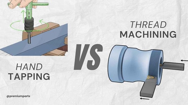
• Thread size
Use a bigger thread size where possible to ease the machining of your part. This is because the smaller the tap, the higher the chances of breakage during tapping. The #0-80 is the minimum thread size, while the M2 or larger is the recommend thread size for CNC machining operations.
For thread length, a thread longer than 3 times the nominal hole diameter is unnecessary, while the minimum thread length is 1.5 times the thread’s nominal diameter. For threads below the M6 size, an unthreaded length equal to 1.5 times the nominal diameter of the thread should be added to the bottom of the hole.

• Text and Lettering
Premium parts can typically CNC-engrave or laser-etch your part to add desired text and letterings. Relative to CNC engraving, laser etching is more cost effective and flexible.
If CNC texts and letterings are part of your design requirement, ensure that you opt for engraving over the embossing. Also, stick to these rules of thumb:
I. Ensure the engraved line has at least 1mm diameter. Also, ensure that it has at least 0.2mm in depth for clear and easy reading.
II. Use Sans-serif fonts like Arial or Verdana.
III. Try to avoid raised text.

• Feature height
Keep the height of all machined features lesser than 4 times the width of such features. This is because taller features than this will vibrate doing machining, resulting in poor tolerances, surface finish, dimensional accuracy, and stability. Also, where possible, use ribs and gussets to reinforce tall, isolated features.

• Tapped holes
Tapped holes may be thru or blind. Where possible, design your CNC parts with thru-holes to facilitate chip evacuation. For tapped holes, ensure that the hole’s depth is not more than 3 times the diameter. For blind holes, add a length over the threaded length that is 1.5 times the thread’s nominal diameter at the bottom of the hole.

• Chamfers and Deburrs
Only model a chamfer if you are particular about its dimensions and angles. Generally, machine shops will break all sharp edges in your design. You also may include a note in your drawing indicating “break edge” or “break all sharp corners.” Keep the chamfer angle at the standard 45 degrees, but you may specify otherwise if another angle is required in your design.

• External corners
Add small fillets to external corners in your part design. These external corners are a natural consequence of machining around that part of the design. Any radius will work, and external fillets will reduce sharp edges and stress accumulation at the corners. External fillets also help eliminate weak corners that can cause damage or scratches to other components or users.

• Undercuts
Undercuts are quite difficult to machine and often require a special type of tooling. The effect of this is longer leadtimes and higher costs. Where and when unavoidable, use the smallest amount of undercuts possible.
There are T-slot and Dovetail undercuts. When designing for CNC machining, ensure enough space for the tool to access the undercut. As a rule of thumb, ensure that the space between the machined wall and other internal walls is at least 4 times the undercut’s depth.
For T-slot undercuts, keep the width of the feature between 3 to 40mm. For dovetail undercuts, the standard angles are 45 or 60 degrees, while the depth of undercut is the ratio of the diameter of the shaft to that cutting blade diameter and is a 1:2 ratio.

• Aesthetic features
Where and when possible, do away with non-critical components and features that are purely aesthetic in your CNC design. You can make a better design by paying more attention to the necessary and critical design features and focus on implementing aesthetics during post-machining processes.
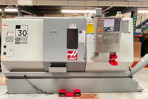
• Size limitations
Each machine shop will have a limitation to the size of the part that can be machined. Ensure that you confirm with your manufacturing partners, and avoid designing parts bigger than their machine capabilities. At Premium Parts, the following are our size limitations:
I. Our maximum dimensions for 5-axis CNC machining are 1000mm * 90mm * 600mm.
II. Our maximum dimensions for 4-axis CNC machining are 900mm * 600mm * 600mm.
III. Our maximum dimensions for 3-axis CNC machining are 1600mm * 1100mm * 900mm.
• 3D Profiles
Unless necessary, try as much as possible to avoid complex 3D surfaces and geometries. This is because 3D profiles slow down the rate of machining drastically. 3D profiles are usually employed to make non-prismatic features of molds, dies, and end-products.

Upload Your Design Now!
Ready to get started or need more details? Click here to get in touch with us, upload your CAD file, and get a free quote and design-for-manufacturability analysis. Our engineers will evaluate your design and point out areas for design improvement, cost-effectiveness, and better functionality.