DESIGN GUIDELINES FOR DIE CASTING
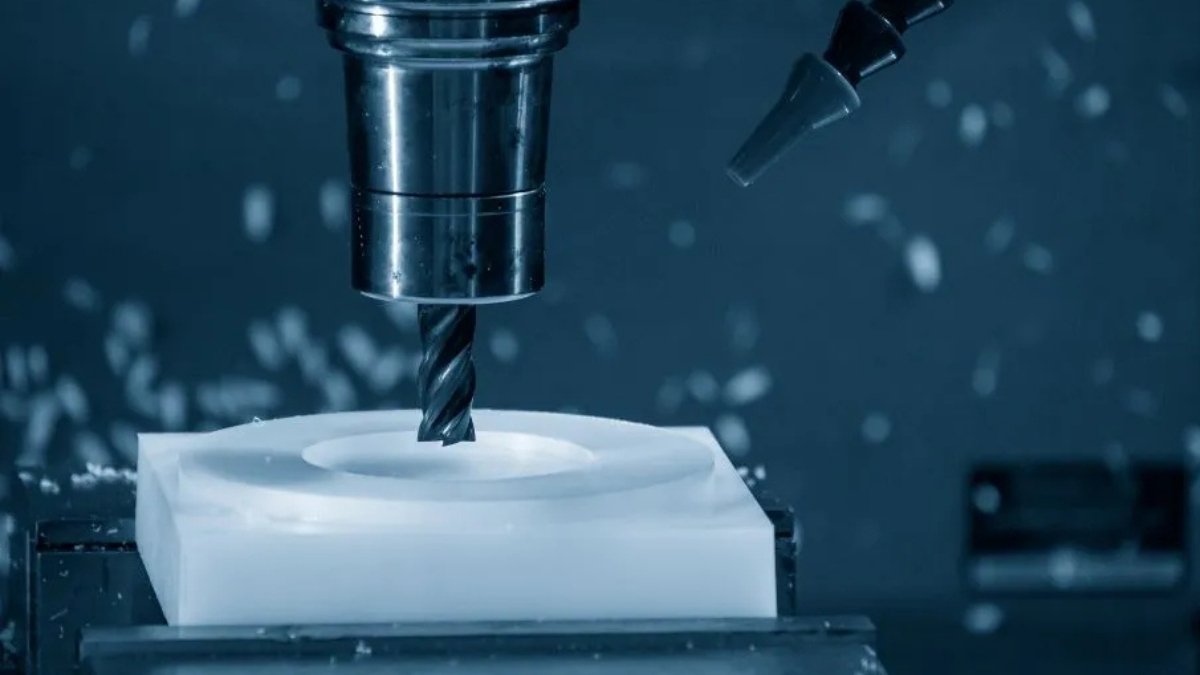
Die casting is the most widely used solution for creating metal parts with high accuracy and dimensional stability. The die casting process relies mainly on process control and optimized parameters to ensure that manufactured parts are defect-free and made to specifications. Another solution to ensuring design excellence for metal die casting operations is adhering to design-for-manufacturability (DFM) guidelines. Premium Parts has put together the best design guidelines to help all our clients make better parts to increase success, shorter leadtimes, and higher functionality. This article summarizes our die casting design guidelines and touches on the use of support structures like ribs and fillets.
• Ribs
Ribs are used to increase the strength of casting without increasing its thickness. Ribs should be blended with radii and fillets where possible to prevent rapid changes in cross-sections, improve die filling, reduce stress concentrations, and eliminate sharp corners. The best type of rib designs are shallow, rounded, and well spaced-out, as they are less likely to distort the casting on ejection from the die.
Ribs often add more strength to castings than solid materials. This is because there is a lower risk of porosity with ribs. They also strengthen ejector pin locations. When designing your ribs, ensure that you avoid thick sections at points where ribs intersect as this may lead to shrinkage porosity.

• Walls
When designing your parts for casting, ensure that you maintain uniformity in your part’s wall thicknesses. Die casting is one of the few metal production solutions that can create parts with a thin wall. Ensure that you take advantage of this and keep your walls thin to save cost, reduce cooling times, and reduce material usage. Endeavor to match the wall thickness to the application of the part and avoid making walls unnecessarily thick.
The minimum wall thickness for die casting is 1mm, but more may be needed depending on the cross-section area and part application.

• Sharp corners
Sharp corners and sharp angles are bad for your design. Sharp angles can result in cooling problems like hot spots, differential cooling rates, and, consequently, distortion defects and shrinkage teams. When designing your casting, avoid long, sharp corners that project in a direction normal to the parting line, as these may result in spalled edges. Instead, use fillets and external radii (covered below) in your design to enhance material flow, reduce stress concentrations, and avoid defects.

• Radii/Fillets
As discussed above, radii and fillets should be used to prevent the weaknesses that arise in sharp corners. You must avoid sharp corners in your design, especially in places where there is a rapid change in cross-section in the part design. Even with the smallest fillets, castings can gain appreciable strength and reduced tension. At the minimum, a radius of 0.4mm is recommended in place of sharp edges. Radii can be larger where permitted but can be limited to 0.8mm if they are to be inconspicuous.
The inside edges should use a fillet with at least the part’s thickness, while an external radius that is at least the internal radii plus the part thickness is recommended. I.e. Rext = Rint + Thickness.
Adding fillets and radii improve metal flow, reduce die cost, and facilitate the durability of the finishing services applied to the part.
Where the external corner cannot have a radius (Rext = 0), keep the internal radius Rint within 1 to 1.25 times the thickness of the wall. At parts with Tee junctions, keep the radius at least equal to the thickness of the feature but no more than 1.25 the thickness.

Where R = External radius, r = internal radius and t = thickness
• Thick/Heavy Sections
Reduce the volume of metal material that will be required to produce your part by coring out thick/heavy sections. The more metal needed in making your part, the longer it takes to fill the die, the longer the cooling time, casting cycle, and overall part cost.
You can also reduce thick/heavy sections by designing pockets or thinner sections supported by ribs. Pay attention to cores’ size and location as poor positioning of pockets can cause inconsistent and non-uniform shrinkage.

• Draft Angles
A draft angle is a slight taper on the side of the cavity sides that facilitate the casting’s ejection from the die. Draft angles aid the ejector pins to push out the casting, and the lack of a draft may affect ejection or cause cosmetic defects and distortions in the part. At a minimum, keep your draft angles at 2 degrees.

• Parting line
The parting line is the line where two parts of the die intersect. When designing your casting, ensure that the parting line is as straight as possible. Consider the part geometry, undercuts, drafts, flash, and draw before positioning the die parting line.
• Text and Lettering
Die casting letterings, numbers, trademarks, instructions, prints, and markings must all be designed to facilitate die construction and die removal. From the design standpoint, the text or lettering should be raised as it is easier to cut a design into the die surface than making the raised design on the surface of the casting. As a rule of thumb, use Sans Serif fonts that are equal to or larger than 20 points, with at least 0.020 inches of thickness. Also, keep your engraving on the surface that lies parallel or near-parallel to the die parting line.
When engraved text may not project above the casting’s surrounding surface, engrave it on a panel that is to be sunk into the casting’s surface. Where possible, avoid depressing texts as they are more expensive and deteriorate with time.

• Crowning
Avoid flat surfaces as much as possible, as they only highlight design or casting imperfections. They also consume a lot of material. Where unavoidable, ensure that the corners of the surface are rounded and “crowned” to improve surface appearance, promote material flow, and reduce distortion.
• Shrinkage
All molten metals will shrink on cooling. This is why designers have to factor in shrinkage rates into dimensioning their parts. The rate of shrinkage will vary from material to material. While shrinkage aids part release from the die in the outer edges, the internal die sections are usually locked in and difficult to remove. The effects of shrinkage can be countered by including a “draft angle” in your part or using a greater draft at points where shrinkage is likelier to happen.

• Uniform Cross Section
Having a uniform cross-section can accelerate the metal flow and casting cycle. When designing your parts, ensure that you do not have excessive changes in the cross-section. Where there are to be changed in the cross-section of the casting, make the changes gradually to avoid porosity and irregular shrinkage. Wherever possible, use ribs and blend them with fillets and external radii to remove sharp corners and ease the changes in cross-section.

Bad design
X Sharp edges
X No chamfer or fillets
X Sharp transition and changes in cross-section

Good design
✓ Transitions are gradual
✓ Use of fillets and/or chamfered edges
✓ The length of the transition section is at least 3 times the height of the feature.
Upload Your Design Now!
Ready to get started or need more details? Get in touch with us, upload your CAD file, and get a free quote and design-for-manufacturability analysis. Our engineers will evaluate your design and point out areas for design improvement, cost-effectiveness, and better functionality.