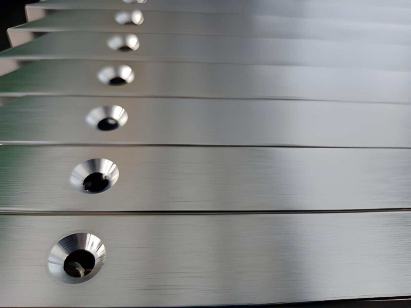
CNC Machining accuracy is not based only on the machine. It also depends on the operator’s expertise. The way you manage every detail, especially the ones most machinists overlook, makes a big difference.
Tool offset is the most common but compromised aspect. It is a fundamental element that has a silent and significant impact on establishing precision, reproducibility, and surface finish.
It does not merely imply entering figures in a control panel. But it’s about aligning digital expectations with practicality. When handled well, tool offset gives consistent part quality. However, it is the silent contributor to scrap, rework, and customer complaints when overlooked.
While many sources skip the basics, this guide focuses on what machinists and engineers use daily, tool offset as a practical solution to common machining challenges. Let’s break it down, identify the typical pitfalls, and examine what is happening on the shop floor today.
What Is Tool Offset: From a Machinist’s Perspective?
In practice, tool offset is a correction applied to align the actual position of the cutting tool with the digital machine instructions. It is not a theory. In fact, it is an ongoing compromise between the anticipated toolpath and the real-world application.
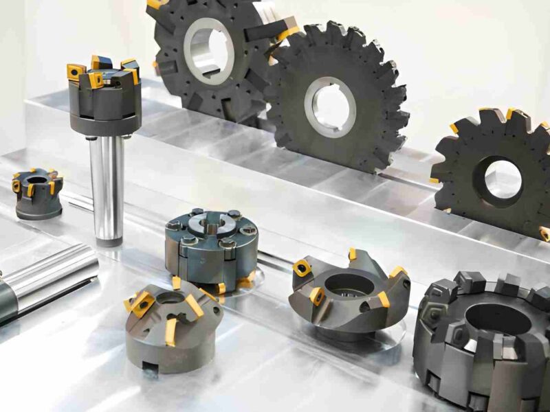
Every CNC machine shop has its concept of zero position. However, each of the tools you mount has a specific geometry, including length, diameter, shape, and wear condition. The machine must understand precisely the tip position of that particular tool about its internal zero point. That’s what the tool offset indicates.
Generally, tool offset includes:
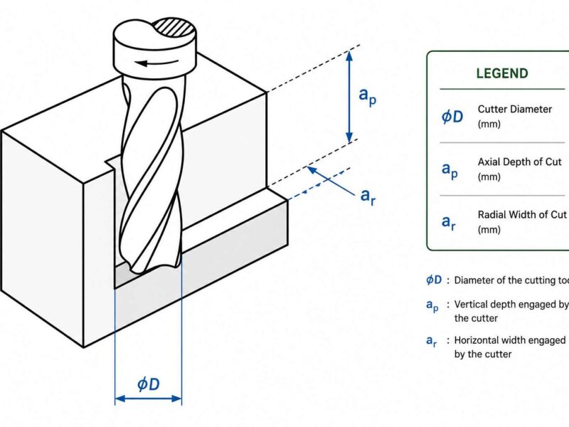
- Tool length offset: It is the distance that the tool tip protrudes beyond the spindle face.
- Tool radius offset: Tool radius offset is applicable in contouring and profiling applications.
- Wear offset and geometry: These are adjustments that are done as a result of tool wear or regrinding.
Tool offsets are dynamic as opposed to setup sheets or CAD models. They shift with tool changes, temperature, and machine drift. You are not merely creating a tool to be the size of something, but you are trying to control its behavior over time.
Skilled machinists frequently use offset values to ensure precise sizes, as well as to manage chip load and tool life. It is not an input that can be done once; it is a control mechanism that is changing.
Tool Offset Errors & Their Root Causes
In even the most advanced machines, Tool Offset errors still extend to a significant percentage of dimensional errors. It is not a problem with the tooling, but the way we handle the positioning of the tool.
The most common obstacles that can emerge due to the offsets and their most common causes are listed here:
1. Incorrect Tool Length Measurement
Sometimes the operators put wrong values in tool length offsets, and this is more prone to occur in cases where the operators change between manual and automated tool setting methods. The existence of cumulative error in multi-tool layouts is brought about by the employment of a feeler gauge or a block that does not have a stable reference.
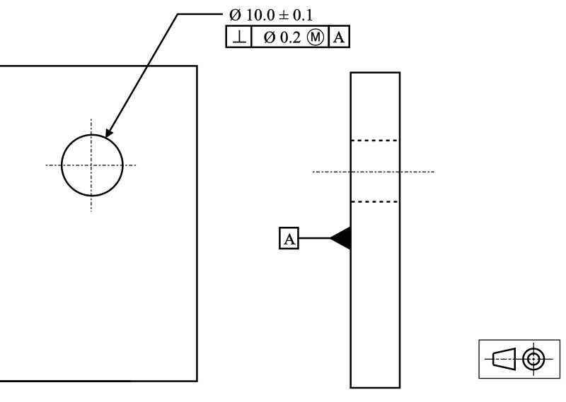
2. Mismatched Work Coordinate System (WCS)
Once the tool and the work offset are not aligned, i.e., due to wrong G54-G59 selection or incorrect probe orientation, it will result in a machined object being put in the incorrect place. It is an aspect that might go unnoticed till it is inspected at the last minute.
3. Tool Wear Not Compensated
Each time there is a cycle, the cutting edge of the tool wears out. Inabilities to keep up with the wear offset lead to the gradual drift of parts out of tolerance. This can lead to failure of entire batches when working on high-precision tasks.
4. Machine Calibration Drift
Thermal expansion and mechanical backlash of machines change machine accuracy with time. The cutting position is different, though the tool offset remains the same. When there is no regular recalibration, the results will be misleading.
5. Operator Input Errors
Even the best program could be derailed with errors in manual data entry. These are wrong signs, decimal errors, and swapped offset numbers. A regular verification routine is not in place to look into such errors before it is too late.
Problems with tool offset hardly occur independently. They creep up on you, and unless your staff is continuously observing them, they present themselves through reworks, rejected components, or early tool wear.
Tool Offset vs. Work Offset: Why Confusion Persists
Tool offsets and work offsets are conceptually distinct. These concepts can be easily confused, even by experienced operators.
Here’s a simple overview:
- Tool Offset specifies the machine’s position relative to the tooltip.
- Work Offset informs the machine of the location of part zero.
The mix-up typically occurs during the setup process. Particularly when manual probing is used, and when changes in parts and programs are made. Operators may even alter one when they want to modify the other. To illustrate, misalignment and scrap occur when the incorrect G54 work offset is used instead of the tool offset as compensation for the part location.
This confusion is more common in multi-setup jobs and involves the use of fixture plates. Throw in various conventions between FANUC, Siemens, or Heidenhain controls, and you have a formula for minor and repeated mistakes.
To mitigate confusion:
- Keep an offset assignment standard.
- Always label offsets with part program references.
- Automate the identification of WCS and tool length measurement by using digital probing. For example, you can use a tool setter to automatically measure each tool length when it’s loaded into the machine or use a touch probe to accurately set the work offset by probing the part’s features.
With such practices in place, tool offset and work offset become effective means.
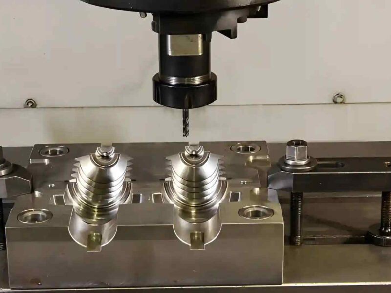
Optimizing Tool Offsets for Multi-Axis and Complex Part Machining
Tool offset plans are critical. This becomes more complicated when you move beyond 3-axis machining. Minor discrepancies in tool location are magnified when rotary tables or tilting heads are involved.
In 4-axis and 5-axis CNC machining, the tool orientation varies during the cutting cycle. The machine’s knowledge about the tool length and geometry should be dynamic. The single-axis fixed offset is no longer accurate enough.
Common challenges in multi-axis setups:
- The tooltip position moves with B- or C-axis rotation and will affect Z-height unless compensated.
- Cutter compensation should take into account multiple angles, not just X/Y paths.
- Recalculated offsets and probing on machines are necessary in cases where there are differences in the height between rotary axes.
Static offsets are still being used in many shops for dynamic toolpaths. These often cause dimensional problems. Here is a way to tackle these issues:
- Re-measuring tool length and tool position after each rotation cycle by use of machine probing routines.
- Kinematic compensation on the more advanced controls, such as Siemens TRAORI or Heidenhain Cycle 32.
Offsets can be simulated digitally using CAM software, specifically, with the programming of 5-axis simultaneous cuts.
In the absence of these controls, even minor errors in the offset table lead to defects that can only be detected at final inspection. High precision manufacturing shops match tool offset management with machine kinematics and process simulation.
Best Practices for Managing Tool Offsets
A well-managed offset system is not about incorporating fancy tools. The majority of the machining inaccuracies associated with tool offsets are due to unorganized tables, old values, and ambiguous procedures.
Here are the best practices that have been proven to assist you;
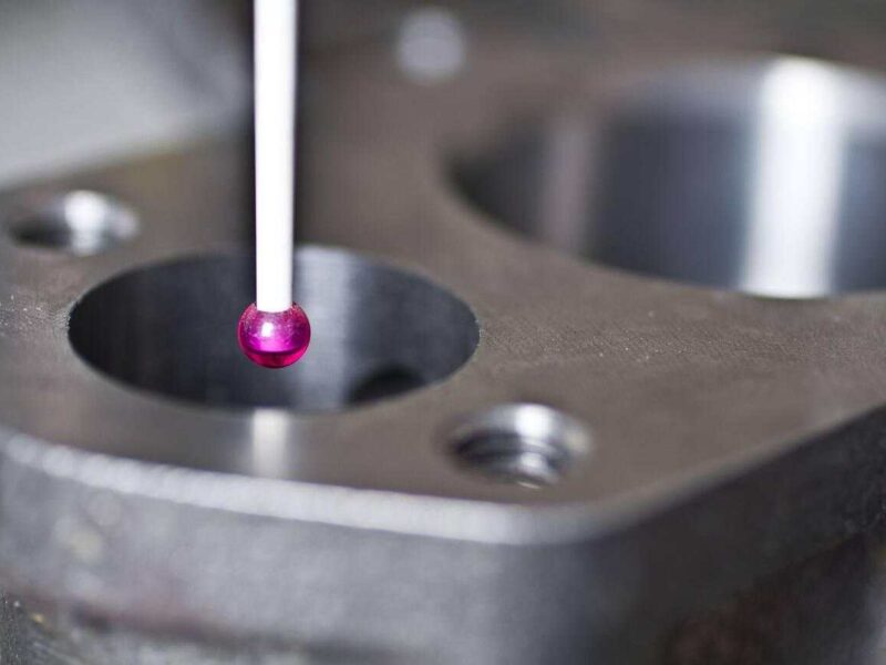
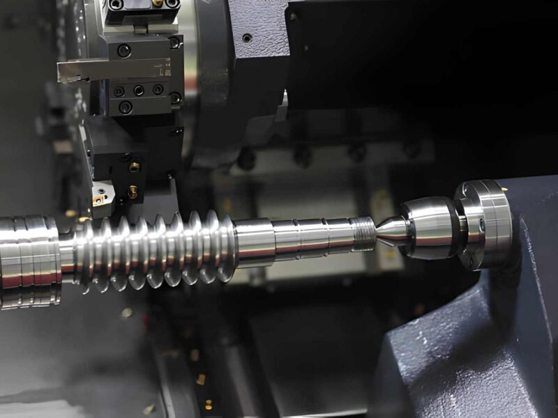
1. Use Touch Probes for Real-Time Measurement
Tool length and diameter can be automatically set at setup using touch probes. More to the point, they can be rechecked during the machining process. So, it allows you to exclude guesswork and downtime as well.
2. Calibrate Tools at Every Batch Start
Even when using the same tools from the same supplier, slight variations can still occur. Measurement tools should always be re-measured before a new run. It is particularly when dealing with high precision machined parts.
3. Store Tool Data with Unique IDs
Assign the tools a digital ID and store their offsets in a centralized library. This avoids confusion when reusing tools and switching jobs.
4. Standardize Offset Entry Routines
Create checklists and macros to facilitate the entry of offsets. For example, pre-set roughing, finishing, and slotting tool offset numbers. This eliminates errors and improves repeatability.
5. Train Operators on G43/G49 Dynamics
Most offset problems are caused by incorrect G43 (tool length compensation on) or G49 (tool length compensation off) commands. So, make sure that the offsets are associated with the active tool number for every operator.
6. Sync CAM and CNC Offset Data
During the production of the toolpaths, CAM software can make use of hypothetical tool lengths. In case these values do not reflect the actual machine entries, then the outcome will not be correct. Make your CAM post-processor in sync to draw live offsets where it can.
7. Adopt Wear Offset to Long Runs
Changing the leading tool offset after the occurrence of wear should be replaced by wear offsets. This keeps you on the same line with your base values, and it is not a problem to backtrack in case something goes wrong.
Poor Tool Offset Impact on Surface Finish and Tolerances
Tool offset not only involves the issue of whether a part is dimensionally correct or not. It has a huge impact on surface finish and the life of tools. Besides, it affects process stability, especially in close-tolerance work.
In case of the misuse of updating the tool offset, it will result in:
- Too deep or too shallow.
- The chip load is not even, and vibration or chatter occurs.
- Over-removal of extra materials raises heat, compromising the finishing.
- Tolerances creep out of spec, slow at first, then all of a sudden.
Here is an example of a medical sector case. Tolerance band was +0.01 -.01mm. A minor mistake in the tool length compensation led to an increment of 0.015 mm only in the Z-depth.
The result: surface integrity was not optimal, and the post-machining check failed even after the right toolpaths and materials were used.
Small parts also have offset errors multiplied on them. A 0.1mm movement might be unnoticeable in a huge mold cavity, but a disaster in the context of watch parts or surgical instruments.
Tool offset should turn into a quality variable instead of a setup process, particularly when your shop has to deal with either regular cosmetic and essential finish requirements. It implies that it has to be checked, both at the very beginning and at certain time intervals throughout the production run.
What to Do When Offset Tables Get Overcomplicated
Offset tables should help operators to understand values, not confuse them. However, with more programs being run by machines and more tools being juggled by shops, it becomes easy to have the offset page cluttered with obsolete, duplicated, and mislabeled values.
Common signs of a messy offset table:
- Multiple offsets for the same tool with unclear purpose.
- Tool number and offset number misalignment.
- Entries that are left over by previous jobs will no longer be used, but are still active.
- Manual “fixes” that override base geometry but aren’t documented.
This creates two major problems:
- Misapplication risk: An operator uses the incorrect offset and scrapes a part.
- Poor troubleshooting: It makes QA or maintenance more difficult to isolate problems.
Here’s how to deal with it:
- Clear out entries that are not used and make changes to entries in a standard document.
- Apply meaningful naming, particularly in shops with advanced control and offset labels.
- Temporary adjustments are color-coded and flagged to be cleared once a batch is complete.
- Set and reset tool offsets automatically by job type with macros.
Offset management isn’t simple. However, if done right, it can save you time in setting up, increase operator confidence, and maintain your part precision. It is a minor adjustment that yields tremendous outcomes when applied strategically.
Final Verdict!
Tool offset is not just a data point. It is a control strategy. When used in moderation, it saves you cost, your part tolerances, streamlines your toolpath, and maintains your scrap rates at a low level. However, when it is not managed, it adds an invisible risk to any production cycle.
Where tool offset is taken seriously in shops, it results in more predictable results. When teams communicate more effectively, fewer assumptions are made, and there is less stress. Efficient shops do not resort to guesswork; instead, they rely on optimized and effective systems.
With increasingly sophisticated capabilities of machines and increasingly sophisticated parts, tool offset becomes less of a technical edge and more of a basic necessity. Accuracy nowadays is not merely a matter of how well a machine can cut. It determines how smart its operators can manage and perfect the process at all stages, beginning with the tool offset.
At Premium Parts, we found out precision begins with preparation, not correction. When you want to minimize your margin of error, increase consistency when switching tools, or work with parts with tight tolerances with greater confidence, we can help. Contact our team about better solutions for your machining issues.