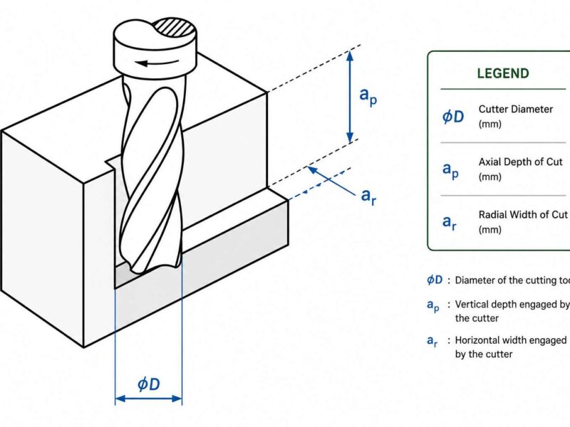
In CNC machining, achieving an exact 90-degree relationship between features is a measurable, controllable, and inspectable requirement. Whether it is a flange face produced by milling, a bearing bore generated with a boring cycle, or a fastener hole created through a drilling operation, the perpendicular relationship of that feature will directly impact how the part is assembled and performs. Perpendicularity in GD&T is a formal means of defining this relationship.
GD&T is an orientation control that constrains a surface, an axis, or a center plane to be contained within a tolerance zone that is oriented at exactly 90 degrees from a specified datum. Unlike a standard angular dimension on a drawing, the GD&T perpendicular callout provides a uniform, three-dimensional tolerance zone for the feature, which is not affected by the height of the feature. Thus, it provides CNC machinists and quality control engineers with an accurate, repeatable reference point for machining and inspection.
Perpendicularity, as defined by ASME Y14.5 and ISO 1101, is a formal control for orientation that specifies how accurately an axis, surface, or center plane must be oriented at exactly right angles (90 degrees) relative to a specified datum. Unlike a basic angular tolerance, perpendicularity establishes a three-dimensional tolerance zone that is directly integrated into GD&T’s overall system of geometric dimensioning and tolerancing (GD&T).
This article provides information regarding all that design and manufacturing engineers need to understand about the GD&T perpendicularity symbol and the proper measurement techniques, and real-world examples of its use.
What Is Perpendicularity in GD&T?
Perpendicularity in GD&T is an orientation control that limits how a feature must be located inside a specific tolerance zone oriented exactly 90 degrees to a datum plane or datum axis. Orientation controls include perpendicularity, angularity, and parallelism.
The basic concept is that the controlled feature (flat surface, cylindrical axis, center plane) must be completely contained within the tolerance zone that is defined. The tolerance zone will always be perpendicular to the referenced datum. Perpendicularity does not directly control either the size or the position of the feature; it only controls the angular orientation of that feature, which is why it is frequently seen used in conjunction with size tolerances, position controls, and profile tolerances on complex engineering drawings.
The Perpendicularity GD&T Symbol
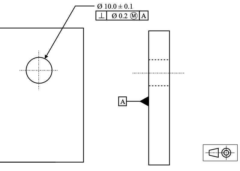
The GD&T perpendicularity symbol, which looks like the mathematical perpendicularity sign (⊥), is a small upright angle used to specify features that must be perpendicular. On a feature control frame, this symbol is the first entry of three; the second entry specifies a tolerance value, and the third entry specifies a datum reference. For example, if a feature control frame states ⊥ | 0.05 | A, the controlled feature must be perpendicular to datum A with a tolerance of 0.05 mm.
In addition to the above symbols, the feature control frame may contain other modifier symbols such as MMC (Maximum Material Condition ⓜ) or LMC (Least Material Condition ⓛ). These modifiers allow for the calculation of bonus tolerances, which can significantly enhance the designer’s flexibility if functional clearances permit. Here are the details of each symbol:
- ⊥ (Perpendicularity Symbol)The first symbol that is entered in a feature control frame determines primary orientation control.
- ⌀ (Diameter Symbol): Precedes the value of tolerance and establishes the cylindrical tolerance zone of the axis of control.
- Ⓜ (MMC – Maximum Material Condition): Tolerance applies at maximum material condition. The feature bonus tolerance accumulates when the feature is away from the highest mass constraint.
- Ⓛ (LMC – Least Material Condition): Tolerance applies at least to a material condition possible due to manufacturing concerns about the minimum wall thickness of an edge condition.
- RFS (Regardless of Feature Size – no symbol, default): The fixed tolerance will be applied regardless of the actual size of the feature, which represents the most restricting set of conditions.
Types of Perpendicularity in GD&T
Perpendicularity in GD&T has two main approaches to control and therefore creates two different types of tolerance (zones). Understanding the differences between these two types of tolerance is critical for interpreting and inspecting engineering drawings correctly.
1. Surface Perpendicularity
Surface perpendicularity controls the flat surface of a part to a datum plane. The tolerance zone created from this type of control consists of two parallel planes separated by the specified tolerance, and oriented such that both planes are at exactly 90 degrees to the datum. All points on the controlled surface must be located between these two planes.
This type of control is typically applied to mounting flanges, as well as to mating surfaces on housings and machined shoulders where both the flatness and angular orientation of the surfaces affect the performance of their assemblies. Additionally, surface perpendicularity indirectly controls flatness. Therefore, as long as a surface lies in the perpendicular tolerance zone, it cannot deviate from flatness by more than that amount of tolerance.
2. Axis Perpendicularity
Axis perpendicularity specifies the relationship of a cylindrical feature’s (i.e., bore or boss) derived axis to a datum plane or datum axis. The tolerance zone for Axis Perpendicularity is a cylinder of the specified diameter, which is oriented perpendicular to the datum. The derived axis of the controlled feature must be entirely contained within this cylindrical zone.
Axis Perpendicularity is critical for drilled holes, clearance holes for threaded fasteners, pin holes, and shafts that are intended to connect to other components that are perpendicular. When the ⓜ modifier applies, the cylindrical tolerance zone will increase as the feature moves away from its maximum material condition, thus providing the manufacturer with flexibility while maintaining functionality.
The following table summarizes the major differences in surface and axis perpendicularity:
| Attribute | Surface Perpendicularity | Axis Perpendicularity |
| Controlled Feature | Flat surface | Cylindrical axis or center plane |
| Tolerance Zone Shape | Two parallel planes | Cylinder (when the diameter symbol used) |
| Datum Reference | Datum plane | Datum plane or datum axis |
| Implicit Control | Also controls flatness | Controls the tilt of the bore/boss axis |
| Common Applications | Flanges, mating faces, and shoulders | Bores, pins, fastener holes, shafts |
| MMC Modifier Applicable | No (surfaces have no size) | Yes (cylindrical features have size) |
Understanding the Perpendicularity Tolerance Zone
The tolerance zone is the key component of a GD&T specification; perpendicularity is no different. Engineers need a full understanding of its geometry to properly define tolerances, inspect products, and resolve functional failures.
Surface Perpendicularity Tolerance Zone
For surface perpendicularity, the zone is defined by two coplanar planes in space that are separated by the perpendicularly defined tolerance value t between them; furthermore, the surfaces must lie in the same plane that is perpendicular to the referenced datum at all 3 planes. This means that all parts of the controlled surface will fall within this sandwiched area at all times.
Axis Perpendicularity Tolerance Zone
For axis perpendicularity without a diameter modifier, like with surface perpendicularity, the zone is 2 parallel and coplanar planes. However, if the diameter symbol ⌀ is used before the tolerance value in the feature control frame, the zone will be defined as a cylindrical volume with a diameter equal to the same tolerance value t. The same zone may tilt or rotate in any direction. It will properly represent functional characteristics for a round feature like pin bores when viewed in relation to the cylindrical zone defined above.
It should be emphasized that the GD&T defines perpendicularity only and does not control the location of any feature. Therefore, the bore axis can be true perpendicular or 90° away from nominal; separate from the perpendicular control is another that defines position in many instances where critical holes are used on parts that both positional and perpendicularity controls will appear on the same drawing to provide the complete definition of the geometric requirement.
Perpendicularity Tolerance vs. Angular Tolerance: Key Differences
There are times when engineers question the use of GD&T perpendicularity instead of a ±angle tolerance on the drawing. The differences in how each type of tolerance interacts with the realities of manufacturing and inspection are the reasons why it’s important.
| Criterion | Angular Tolerance (±°) | GD&T Perpendicularity |
| Tolerance Zone Geometry | Fan-shaped (wedge) | Uniform width (two planes or cylinder) |
| Datum Reference Required | No | Yes – always references a datum |
| Effect at Feature Size | Tolerance widens with distance from the vertex | Uniform regardless of feature size |
| MMC/LMC Modifiers | Not applicable | Applicable for the feature-of-size |
| Inspection Method | Angle measurement (protractor/CMM) | Surface plate, sine bar, CMM, height gauge |
| Drawing Intent Clarity | Ambiguous at 90° | Unambiguous – standard GD&T control |
An angular tolerance forms a wedge-shaped tolerance zone and becomes wider as you move away from the angle vertex, which is not functional in most engineering applications. The GD&T perpendicularity callout creates a continuous tolerance zone with a constant width and therefore, provides consistent functional control on the entire feature.
How to Measure Perpendicularity in GD&T?
In order to measure perpendicularity properly within the framework of GD&T systems, you must consider your measurements carefully and how you plan to support your part(s) during your measurement process. The methods for measuring perpendicularity will vary depending if you are measuring the perpendicularity of an axis or the perpendicularity of a face, and the type of equipment you have at your disposal.
Surface Perpendicularity Measurement
To measure the perpendicularity of a face, the most common approach is to use a precision surface plate to create a simulated datum and utilize a dial indicator (using a height gauge or CMM) to scan along the controlled surface. At the same time, the part sits on the datum surface against the plate, and you then read the total indicator reading (TIR) when the indicator is moved from end to end along that feature. Your TIR will tell you how much of the tolerance zone is occupied by that surface. If your TIR is within the tolerance width defined in the tolerance definitions, you can then pass that part.
You can also use a precision square or a granite angle plate as a datum reference for surface perpendicularity checks. If you are working in a high-volume production environment, you may want to utilize custom, go/no-go fixtures, which will speed up the inspection process and maintain the integrity of your measurement.
Axis Perpendicularity Measurement
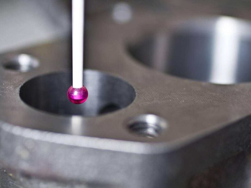
Evaluating axis perpendicularity is more complicated than evaluating any other characteristic. Axis perpendicularity is derived from the physical bore or pin surface by reconstructing a derived axis. A coordinate measuring machine (CMM) is the tool of choice for defining the derived axis. The CMM will define a derived axis by taking multiple probe hits around the two diameters of an intersection between a cylindrical feature and the surface of the feature at a variety of depths. While defining the axis, the CMM will calculate its absolute position relative to the perpendicular datum plane defined by the feature. Thus, it will generate an absolute and relative deviation of that derived axis for each probe hit from the datum plane.
For checks on the shop floor, the combination of a precision pin gauge inserted into the bore with a dial indicator and height gauge provides a practical alternative for determining angle deviation. The pin gauge is representative of the mating shaft, and a comparison of dial indicator reads at the top of the pin to that of the bottom provides a direct measure of the angular deviation that can be converted to a linear zone width.
CMM Perpendicularity Inspection
The method of inspecting the perpendicularity with modern CMM software is done without any human intervention after a datum and feature have been created. The operator creates the datum reference frame by probing the surface of the datum and then probes the controlled feature; the software performs the calculations to determine the perpendicularity deviation and compares that to a value defined by the specification. For perpendicularity of cylindrical axes, most CMM programs return to the operator the deviation of the determined axis from the tolerance limit, both in linear form and in angular form, so that the engineer can see the complete picture of the geometric deviation.
Summary of perpendicularity measurement methods:
| Method | Feature Type | Accuracy Level | Best For |
| Surface plate + dial indicator | Surface | Medium-High | Shop floor, production checks |
| Precision square/angle plate | Surface | Medium | Quick verification, prototype checks |
| CMM (coordinate measuring machine) | Surface & Axis | Very High | Critical parts, documentation, aerospace/automotive |
| Pin gauge + height gauge | Axis (bore) | Medium | Shop floor axis checks |
| Optical comparator/vision system | Surface | Medium | Thin parts, 2D sections |
| Laser tracker | Surface & Axis | Very High | Large parts, structural components |
Engineering Applications of Perpendicularity in GD&T
Manufacturing requires precision when working with parts that will come together as assemblies. The placement of one manufacturing process on another affects the final product’s performance. In cases where the quality of all parts and the consistency of the assembly are important, perpendicularity is critical:
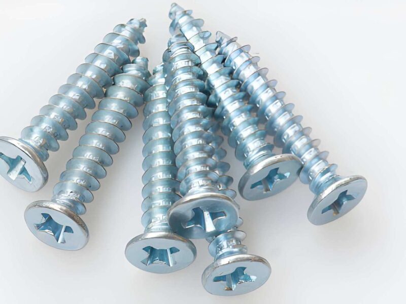
- Flange bolt hole patterns: If the bolt hole axes are not aligned, it can result in cross-threaded holes, varying clamp loads, and early fatigue of fastener components. Tolerances on the axis perpendicularity of the bolt holes ensure that the bolts will always engage properly in all joints when assembled.
- Bearing bores: The axis of the bore on a rolling element bearing must be precisely perpendicular to the datum face of the housing. Any tilt will create internal misalignment loads that can greatly reduce the bearing’s service life.
- Hydraulic manifold bolting surfaces: The perpendicularity of the surfaces on the port areas of the manifold controls whether there will be a leak path or if the O-ring or gasket will seal properly under pressure. Even slight angles of a few micrometers will prevent a proper seal from forming.
- Precision Spindles and Shafts: The shoulder of a shaft must be perpendicular to the shaft axis so that the thrust bearing is properly seated to minimize axial runout and vibration at high-speed rotation.
- Printed Circuit Board Standoffs: The perpendicularity of the axes of the mounting bosses maintains board flatness and connector alignment in electronic assemblies and reduces the mechanical stresses on solder joints.
- For Aerospace Structural Brackets: The precision angular orientation of fixturing features creates the paths for structural loading. GD&T calls out perpendicularity with tight tolerances of 0.02 mm or tighter, defining the limits of expected manufacturing for safety-critical joints.
All three applications have a similar theme of perpendicularity in GD&T; it takes an abstract angle requirement and creates a quantifiable, inspectable, and manufacturable specification that provides the link between design intent and manufacturing realities.
MMC and RFS Modifiers in Perpendicularity GD&T
When the perpendicularity tolerances apply to size features like bore, shaft, or slot, or when the MMC and RFS modifiers apply to static features, they affect the perpendicularity zone depending on the size or Material Condition of the Feature. It’s important to understand Material Condition and the relationship between Material Conditions and tolerances for both design and manufacturing processes.
MMC (Maximum Material Condition) Ⓜ
When a size feature has an MMC, the specified perpendicularity tolerance applies only at the MMC size (i.e., the smallest bore and/or the largest shaft within the MMC limits). When the feature is no longer at MMC, an amount equal to the feature’s departure from MMC will act as a bonus tolerance, which will then be added directly to the perpendicularity tolerance zone to ensure that the maximum yield of the feature can be commonly manufactured while still maintaining the requirements of the function of the completed assembly.
RFS (Regardless of Feature Size)
When a size feature is DRFS, it will have no modifiers or Material Condition; therefore, the perpendicularity tolerance specified has a fixed value and is not dependent on the size of the finished feature. DRFS is the most limiting way to provide tolerances for size features. It’s an appropriate modifier for all types of press fit assemblies, interference fit assemblies, or any size feature for which the angle tolerance would cause the functional assembly to fail, regardless of the size variation from the specified size measurements.
For example, if the required bore is 10.00 mm with an MMC specified at 9.95 mm, and the perpendicularity tolerance at MMC is Ø0.05 mm, then if the measured bore is actually 10.10 mm (or a deviation of 0.15 mm), the effective perpendicularity zone would be increased to Ø0.20 mm. This method of applying perpendicularity in this manner can help manufacturers reduce scrap rates and increase the functional quality of the assembled product.
Frequently Asked Questions
Q1. Does perpendicularity in GD&T also control flatness?
Yes, when controlling the perpendicular orientation of an object. It’s important to place the object on an imaginary plane that bisects the surface into two separate surfaces. The two surfaces must stay within two parallel planes, which is also known as a tolerance zone. Therefore, the object will not deviate from the flatness over those two surfaces by more than their respective tolerance zone widths.
Q2. When should I use perpendicularity instead of position tolerance?
Use a position tolerance when you need to control both the location and orientation of the object. Use a perpendicularity refinement when you need to have your tilt constrained tighter than allowed by your position zone.
Q3. What is a typical perpendicularity tolerance value in machined parts?
It all depends on the functional need. Typical machine-made structural surfaces generally provide a tolerance of 0.1mm to 0.5mm. Precision bearing bores and their associated mating flanges require tolerances of 0.01mm to 0.05mm. Perpendicularity tolerances in the Aerospace and High Precision Spindle applications require tolerances as tight as 0.002mm to 0.020mm. Tolerance values should always be determined using a Tolerance Stack-up Analysis. Over-tolerancing will lead to increased cost to the assembly, whilst under-tolerancing will result in assembly failure.
Conclusion
To summarize, perpendicularity provides an unambiguous, quantifiable, and inspection-friendly means by which engineers can define the 90-degree relationship between a feature and its datum using GD&T. In contrast to a straightforward angular tolerance, it establishes a geometrically accurate, consistent tolerance zone that reflects all functional assembly criteria.
When creating and applying a perpendicularity tolerance in GD&T, engineers ensure proper application. They need to select the appropriate type of tolerance (surface vs. axis), incorporate the proper material condition modifier, identify a distinctly defined datum, and pull from stack-up analysis to pick the correct tolerance range.
Ultimately, this means that the resulting parts will assemble correctly on the first attempt. Thus, they will perform according to the expectations throughout their use, and will be verifiable at all stages of production.
Premium Parts creates and interprets drawings to comply with GD&T specifications such as perpendicularity, position, profile, etc. As a result, we have the engineering capabilities to correctly create components to the specifications required by you. Be it the CNC machining parts or intricate assemblies using sheet metal, we know how to serve you right.