The design of snap-fit joints significantly affects the performance of a product and its associated cost to manufacture. Unlike other fasteners, such as screws or glue, snap-fit joints depend on elastic deformation, which is the temporary shape change of a pin or loop until a mating part passes the interference zone, causing it to return to a fixed position.
Snap-fit joints are designed to use no additional hardware, require fewer bills of materials (BOM), and can be assembled in a single operation without tools on high-speed production lines. Even though snap-fit joints can appear very simple at the time of assembly, they are subject to a complex set of structural, tribological, and manufacturing rules.
Elastic limit, return angle geometry, wall thickness uniformity, and material fatigue shall be designed simultaneously, while an error in any variable will compound the risk of failure or require costly changes.
This guide provides extensive technical resources for the product engineer and tooling team: Joint classification, return angle data, material property comparisons, tolerance management techniques, and failure mode analysis; all based on sound engineering principles instead of marketing generalizations.
What Is Snap Fit Joint Design? Engineering Principles Explained
A snap-fit joint is a method of joining two components together using a locking mechanism. One component contains a protrusion (or hook or bead) that will elastically deform when placed against the mating recess or undercut of the second component.
Once the protrusion clears the obstruction, the elastic strain energy stored is released and causes the protrusion to return to its original or “neutral” position. This process secures the joint together and is classified as “self-locking” because no additional tool or adhesive is required to hold the two components together.
Mechanical Principle for Snap Fit Joint
The principle of controlled elastic deflection governs the design of a snap-fit joint. It is up to the designer to ensure that the maximum amount of strain during assembly stays below the 60%–70% of the yield strain limit for amorphous type polymers, and 50% – 60% of the yield strain limit for semi-crystalline type materials, to prevent any type of permanent or plastic deformation of the material (i.e., cracking).
The cantilever snap-fit joint provides the easiest example of the applications of the elastic deformation principle; it is a simple beam (length L, root width b, and root height h), which has the maximum amount of deflection defined by the following equation:
d_max = (e_perm x L^2) / (1.5 x h) where e_perm = permissible strain, L = beam length, h = root thickness
From this equation, it can be seen that the taper ratio and the length of a beam (L) are the two major design levers for a snap-fit joint design. As L increases, the deflection experienced at the root will also increase, and therefore, the peak root strain decreases for the same amount of deflection.
Likewise, using a taper ratio from the root to the tip of a beam is a method of distributing the strain uniformly through the length of the beam; a design method known to increase fatigue life by up to 30% – 40% in cyclic loading applications.
Types of Snap Fit Joints: A Technical Classification
To properly design a snap-fit joint, you must be familiar with all five basic types of snap-fit geometries. All five types differ in terms of where they deflect, how they transfer loads (the mechanism), and how many times they can be assembled and disassembled.
| Joint Type | Deflection Mode | Releasable? | Best For | Typical Material |
| Cantilever | Bending (lateral) | Yes | Consumer electronics, clips | ABS, Nylon, PP |
| U-Shaped | Bending (extended) | Yes | Space-constrained assemblies | PP, Polycarbonate |
| Annular | Hoop stress (radial) | Conditional | Cylindrical enclosures, caps | HDPE, Nylon |
| L-Shaped | Sliding/tab lock | Yes | Quick-access panels | ABS, POM |
| Torsional | Torsion (twist) | Yes | Repeated attach/detach | POM, Nylon 66 |
Cantilever Snap-Fit Joints
The cantilever design represents the most common type of snap-fit joint. The beam extends out from the base of the component with a tapered hook at the free end. As the snap-fit joint is assembled into the mating component, the cantilever beam bends sideways. When fully assembled, the hook clears the mating surface of the mating component, and the bent cantilever beam springs back to its original position.
The return angle of the hook face will affect the force required to disassemble the snap-fit joint: an angle of 30 degrees will require less force than a back angle approaching 90 degrees, which will create an almost permanently locked snap mechanism. Because the cantilever design is easy to model, mold, and inspect, it has become the preferred design for assemblies such as consumer electronic enclosures, battery doors, and automotive trim clips.
U-Shaped Snap-Fit Joints
The U-shaped snap-fit joint is made to double back the cantilever beam onto itself within the component’s body. The benefit of this design is that it greatly increases the effective length of the beam while maintaining the overall footprint, which is critical in applications where you need to maintain a specific depth dimension. The extension of the length of the beam reduces the root strain for equivalent deflection, thereby improving the fatigue characteristics of the cantilever beam for multi-cycle applications, such as connector housings.
Annular Snap-Fit Joints
These types of snap-fits use hoop stresses rather than bending principles. There’s a circumferential bead on either the shaft or plug engaging with a groove in the round opening of the bore. The removal and assembly forces of the joint rely on the lead angle (ramp that leads into engagement) and the return angle. Entire circumferences can all carry load because the entire circumference of the snap-fits carries substantially higher retention forces per unit of material than a cantilever structure with an identical cross-section. Eyelash style snap-fit joints dominate in pen cap, bottle closure, medical cartridge, and sensor case applications.
Torsional Snap-Fit Joints
Torsional snap-fits rotate rather than bend. A horizontal arm attached to a vertical shaft twists. These types of snap-fits rotate rather than bend. These types of joints are developed by a horizontal arm that is connected to a vertical shaft, which twists as it engages a latch when pushed on by assembly forces. The reason that the torque stiffness for this type of joint is significantly more than the bending stiffness is that torque stiffness is a function of polar moment of inertia, as opposed to area moment of inertia. These types of joints can be designed in a wider range for applications requiring a low insertion force while having high return torque capability.
L-Shaped Snap-Fit Joints
L-shaped Snap-Fit Joints consist of a sliding tab that is inserted into an L-profile channel. The assembly motion is two-directional (sliding, then locking), which provides resistance against axial loads for unintentional disassembly; they may be intentionally released laterally. The load-bearing capability is constrained by the shear area of the tab, and due to the impact of manufacturing tolerances, the primary application is low-load panel retention or packaging enclosures.
Return Angle Engineering in Snap Fit Joint Design
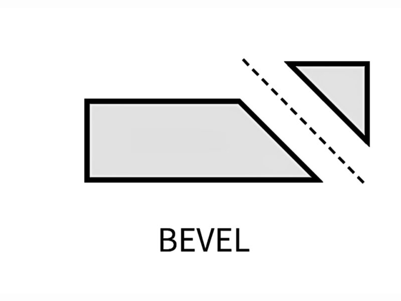
One very powerful parameter for tuning the releasability of a snap-fit joint is the return angle on the locked surface of the snap-fit hook. The return angle generally dictates how much force or resistance is needed to disassemble the joint. The relationship between the return angle and disassembly force can define the approximate disassembly force.
F_removal = F_insertion x tan(a_return) / tan(a_lead) where a_return = return angle, a_lead = lead angle (entry chamfer)
| Return Angle (deg) | Removal Force | Releasability | Recommended Use Case |
| < 30 | Very Low | Easy release | Frequently opened panels, maintenance covers |
| 30-45 | Moderate | Releasable | Consumer product enclosures, battery doors |
| 45-75 | High | Difficult release | Safety-critical covers, child-resistant closures |
| 90 | Maximum | Permanent | Single-assembly structural joints |
In common applications, most injection molded snap-fits use return angles that provide a releasable function, usually at 30-45 degrees. The use of a 90-degree return angle with a true undercut that is perpendicular to the direction of the mold pull requires the use of side-actions or lifters, and in turn, the tooling cost on the mold must be justified by the structural purpose of the joint.
Material Selection for Snap Fit Joint Design
The choice of materials to design parts to snap fit together is crucial with geometry. Three important characteristics of the materials are permissible strain, flexural modulus, and fatigue resistance. A high modulus material, such as POM, will generate greater mating forces between the parts than a low modulus material, such as PP. Still, it will also fail earlier under contact load. Therefore, to produce a successful snap-fit joint, engineers should attempt to balance these two competing properties of the material.
| Material | Tensile Strength (MPa) | Flexural Modulus (GPa) | Max Strain (%) | Fatigue Resistance |
| ABS | 40-55 | 2.0-2.9 | 3-5 | Moderate |
| Polypropylene (PP) | 25-40 | 1.1-1.6 | 10-20 | Good |
| Nylon 66 (PA66) | 70-85 | 2.5-3.2 | 2-4 | Excellent |
| POM (Acetal) | 60-70 | 2.8-3.4 | 3-6 | Excellent |
| Polycarbonate (PC) | 55-75 | 2.2-2.6 | 5-10 | Good |
| PETG | 45-55 | 1.8-2.2 | 4-8 | Moderate |
Several practical guidelines drive material selection decisions:
- Semi-crystalline polymers (polyacetal (POM), nylon (PA66), and polypropylene (PP)) will provide better fatigue resistance than amorphous polymers (acrylonitrile-butadiene-styrene (ABS) and polycarbonate (PC)), because the crystalline lamellae within these materials are effective at stopping crack propagation at the micro-scale.
- Glass-filled will increase the modulus of elasticity, but greatly decrease the allowable strain and fatigue life (Snaps fit together), so only use glass-filled materials for snap-fit hooks with extreme caution and use FEA to verify this.
- POM (Acetal) is the preferred material to use for a snap where the excess of 1,000 engagement cycles occur, because POM is very stiff, has a low coefficient of friction (dry = 0.2-0.3), and has very good fatigue resistance.
- In elevated-temperature environments (> 80°C), standard ABS or PP may creep under sustained snap-fit preload; glass-filled nylon or PEEK should be evaluated instead.
- Chemical compatibility with lubricant, cleaning products, or UV should be confirmed from material Data Sheets, not assumed to conform to generic polymer family Data.
Key Engineering Design Considerations for Snap Fit Joint Design
The successful design of snap-fit connections will require an engineer to manage multiple related variables. Below are the critical variables for reviewing designs:
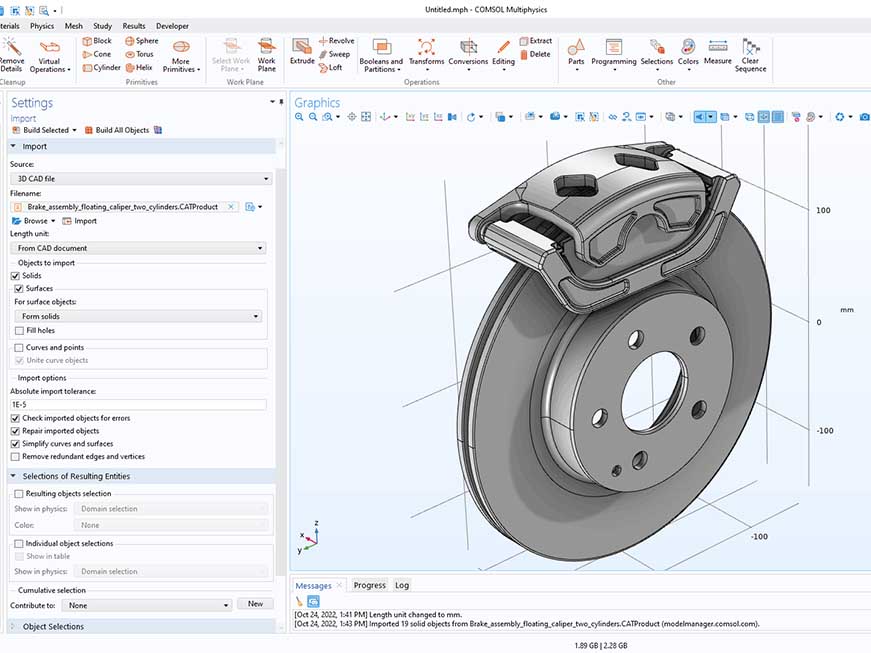
1. Stress and Strain Analysis
All snap-fit joints that will support structural loads or that have more than 20 engagement cycles must have a finite element analysis (FEA). A linear elastic analysis will be adequate for quick validation, but large deflections (d > beam thickness/4) must undergo a nonlinear analysis (i.e., one where material nonlinearity appears). As a rule of thumb, the peak strain experienced by the root of the beam should not exceed 70% of the material’s published yield strain. When selecting snap-fit designs for production parts, design engineers should apply a safety factor of 1.5 to 2.0.
2. Dimensional Tolerance and Clearance Management
Snap-fit performance is highly sensitive to variations in part dimensions. A hook height tolerance of +/-0.05 mm can create a variation of 15%-25% in assembly forces. Designers must follow GD&T principles rigorously and apply true-position tolerances to the components being mated together using hook-and-ledge design features.
For plastic-to-plastic snap-fits, a typical clearance fit of 0.05-0.15 mm should be used. Tighter fits will require higher insertion forces and carry a greater risk of jamming due to worn tooling; looser fits will have a rattling sound, while providing less retention.
3. Fillet Radii at Stress Concentration Points
A sharp corner created at the root of a cantilever can produce high levels of stress concentration (Kt values 2.0 – 3.5). Adding a radius (fillet) to these corners (25% to 50% of beam thickness) will lower Kt to 1.2 to 1.5 and can double the life of the part. Therefore, this is consistently one of the highest return-on-investment structural changes made during design review.
4. Taper Along Beam Length
With a constant cross-section cantilever beam, stress will reach a max at the fixed root and approach zero at the free end, creating an inefficient distribution of stress.
Creating a taper (decrease in cross-sectional thickness) along the length of the cantilever beam will shift the stress profile towards being more uniform by reducing the peak stress at the root by 20 to 35% for the same tip deflection. Typical taper ratio for an injection-molded part will be approximately between 0.5:1 and 0.7:1 from the tip to the root of the beam.
5. Lugs and Over-Insertion Stops
Lugs are small structural ribs that are placed adjacent to the snap fit hook (fastener), which bear shear forces and prevent the hook from carrying bending and shear at the same time.
An over-insertion stop is a small object that prohibits the hook from deflecting to the maximum amount during assembly and helps prevent the operator from applying excessive force on the hook, which may overwhelm the hook’s stress limits. Both the lugs and over-insertion stoppers can be added to the mold design for minimal cost and dramatically increase the reliability of the end-use part.
Advantages and Limitations of Snap Fit Joint Design
While snap-fit joints may offer advantages from an engineering and commercial perspective, there are limitations inherent to this fastening method that must be recognized before implementing it:
Advantages
- No tools required for assembly can save 40-70% on cycle time vs. screw-fastened alternatives in automatic assembly line processes.
- No screws, nuts, and inserts reduce the BOM cost of your product and eliminate the need for a torque control process.
- In some designs, snap-fit joints can be flush with the outer surface of the product, thus increasing their value as part of a product with an IP rating, as there are no visible fasteners on the outside of the product.
- Since all parts of a product can be made of the same material, fewer recyclables must be separated at the end of your product’s useful life. This is a growing concern from both a sustainability and regulatory perspective.
- All modular snap-fit component families can be interchangeable from one family to another, therefore reducing tooling costs.
Limitations
- If not appropriately designed, hooks are highly susceptible to stress concentrations at their roots during both low-cycle fatigue and impact loadings, therefore being very susceptible to failure.
- Long periods of time under compressive load can cause the snap fit to come apart as it eventually relaxes. This is particularly evident with parts made from PP and LDPE when exposed to elevated temperatures.
- After assembly, snap fits are not easy to inspect for defects, and a snap fit will not show if the engagement is partially locked unless force measurements are taken during the assembly process, or the snap fit is tested in a destructive manner.
- Permanent snap-fit joints are difficult to repair without damaging the components. It is important to consider the cost of repairs in your design.
- Variations in the size of parts can create dimensional sensitivity; therefore, the wear of molds and variations from shot to shot can cause parts to be manufactured outside of specification limits without any change in part size.
Frequently Asked Questions
What is the maximum number of engagement cycles a snap-fit joint can withstand?
The number of engagement cycles a snap-fit joint can withstand depends on the material, the amount of strain on the joint, and the geometry of the snap-fit design.
For example, POM snap-fits designed with a 50% allowable strain and a properly radiused root can be engaged and disengaged over 10,000 times with no visible degradation. In contrast, ABS snap-fits will generally fail between 500 and 1500 cycles due to their lower fatigue resistance, but they are also designed to withstand a 50% allowable strain.
Can snap-fit joints be used in metal-to-metal assemblies?
Snap-fit joints can be used in metal-to-metal assemblies; however, metal snap-fit designs must be based on design parameters that differ fundamentally from those used for plastic snap-fits. Engineering materials, such as metals, have lower allowable strains compared to thermoplastics, typically 0.5% to 2% for spring steel and 3% to 20% for thermoplastics.
Therefore, designs for metal snap-fits must use very thin cross-sections, longer beam lengths, or spring configurations such as a leaf spring or stamped tab configuration to avoid yielding and achieve sufficient deflection.
How does the manufacturing process affect snap-fit joint design tolerances?
The manufacturing process has a major effect on the tolerance of the snap-fit joint. For example, injection molded parts can produce mating hook heights within +/- 0.05-0.10 mm reliably with properly maintained tooling, making it the process of choice for high-volume production runs of snap-fit joints.
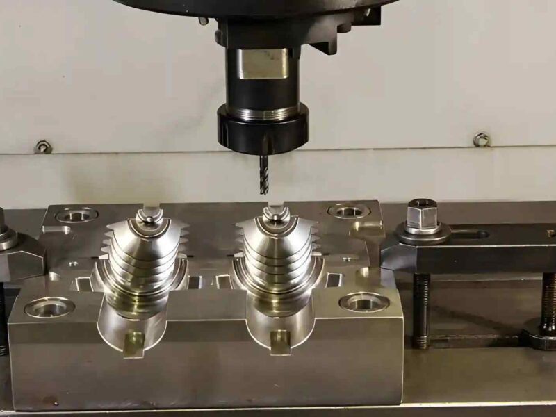
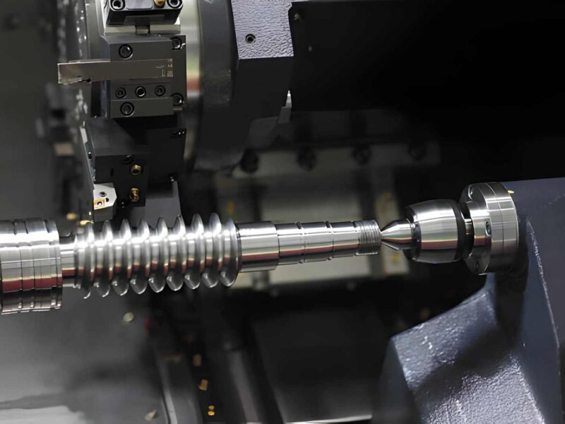
On the other hand, industrial FDM (e.g., Stratasys Fortus) can produce snap-fit features with tolerances of +/- 0.2-0.5 mm, which works well for prototyping but may require design adjustments to achieve production equivalent performance. Both the SLA process and the SLS process have tolerances of +/- 0.1-0.15 mm, making them good choices for functional prototypes. CNC Machining can hold ±0.025 mm; however, only low-volume metal snap-fits or master patterns will be cost-effective with this process.
Conclusion
The design of snap-fit joints is a complex engineering challenge, but one that can yield substantial advantages from an engineering and commercial perspective if done well. Proper use of snap-fit joints requires moving beyond rule-of-thumb guidelines to understanding the mechanics behind them, such as acceptable strain limits, return angles, material fatigue, and tolerance stack- up. Only then do snap-fits become a reliable and high-performing fastening method rather than a source of failure and warranty claims in the field.
At Premium Parts, we design, produce, and manufacture snap-fit components in a wide range of different types of thermoplastic materials and using many different types of production processes, including but not limited to the following: Injection Molding, CNC Machining, and Industrial Grade FDM. Our team works closely with our product designers from the conceptual stage through the production stage to develop FEA (Finite Element Analysis)-validated snap-fit geometries for injection-molded, machined and additively manufactured parts. Contact us now to discuss your next project.