Hardened steel production molds require a substantial investment in cavity machining, fitting, and mold trials. Changes to the design after the tool completion can add high cost and delay.
Prototype tooling employs aluminum or pre-hardened steel and produces molded parts earlier in the development process. These tools enable engineers to evaluate shrinkage, warpage, gate performance, and part fit before the release of production tooling.
This method is useful when CAD and simulation do not predict molding behavior fully. Functional plastic parts are suitable for assembly, mechanical performance, and pilot production testing
We at Premium Parts will review your CAD model before any tooling and identify risks like uneven wall thickness, sharp corners, and tight tolerances. We then provide prototype tooling, injection molding, and inspection services to help verify the design before mass production. This article describes the process, benefits, limitations, and applications of prototype tooling.
What Is Prototype Tooling?
Prototype tooling uses temporary or semi-production molds for low-volume manufacturing. Engineers can use it to verify the performance of a design before spending money on production tooling.
These molds are usually made of aluminum or pre-hardened steel. They are faster to machine and cheaper than hardened production tools. Prototype tooling can produce from dozens to several thousand parts, depending on the material selected and the complexity of the part.
Injection molding, casting, and thermoforming often use prototype tooling. It enables teams to assess assembly fit, mechanical performance, and cosmetic appearance with production-grade materials.
How It Works: Steps Involved in Prototype Tooling
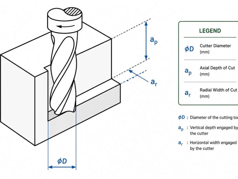
Prototype tooling starts with a detailed CAD model and defined part requirements. Engineers check wall thickness, draft angles, undercut, and tolerance zones. Engineers evaluate gate position and cooling channels to improve filling, minimize warpage, and keep part cooling consistent.
After the design review, the appropriate tool material is selected based on the expected shot volume and resin characteristics. The mold design is then developed, including the cavity layout, runners, vents, and the ejection system to support stable part release and consistent filling.
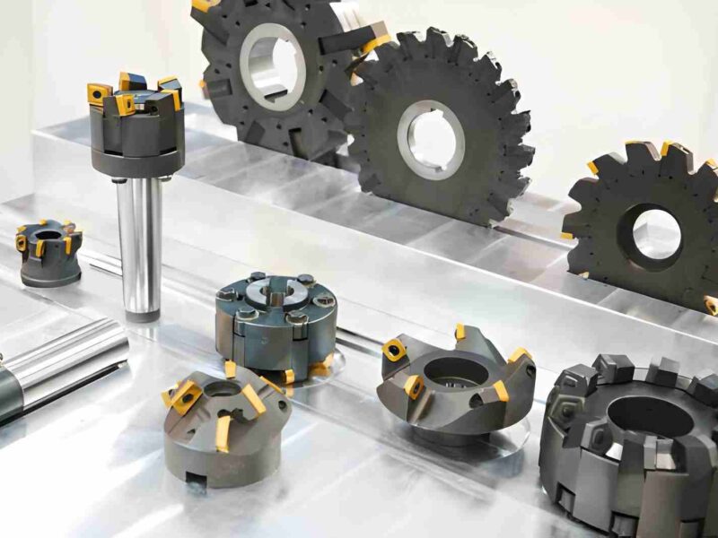
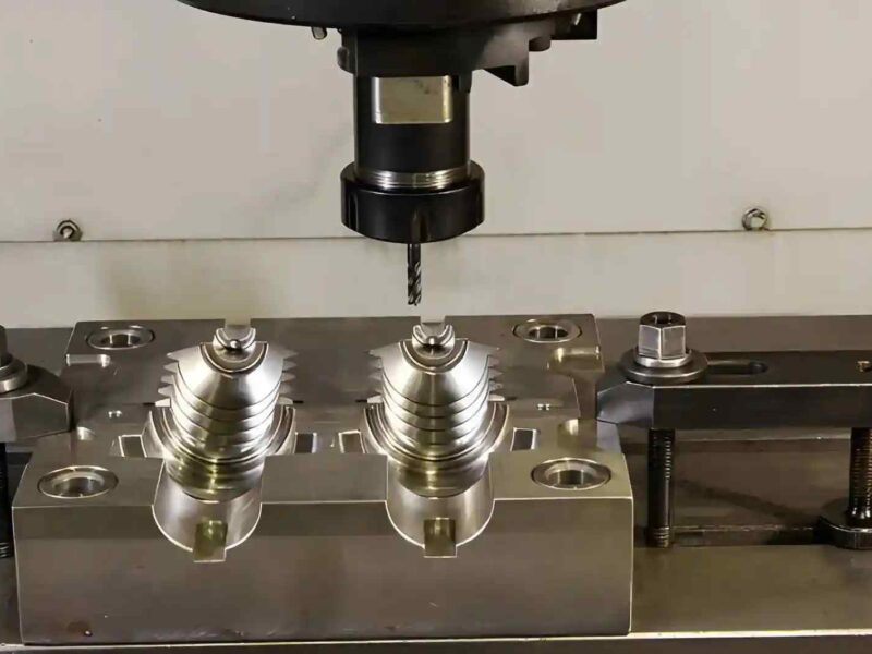
CNC milling produces most mold components. EDM creates sharp corners, narrow ribs, and intricate internal features. Subsequently, the surface of the cavity is finished by polishing or texturing in accordance with functional and cosmetic requirements.
After the mold is assembled, trial runs assess molding behavior and dimensional performance. After trial molding, parts are inspected for short shots, sink marks, flash, weld lines, and warpage. Tool corrections are made through T0, T1, and T2 trials by adjusting gates, cooling, and critical dimensions. After final approval, pilot production begins for testing and initial application use.
What Impacts Prototype Tooling Speed?
Prototype tooling lead time varies with mold complexity, material selection, machining needs, and tolerance requirements. Simple mold geometry and practical tolerances reduce machining, fitting, and inspection time.
Mold Design Complexity
Complex molds demand additional machining, fitting, and trial work. Additional actions, lifters, and multiple cavities add to manufacturing time. Thin cores and deep ribs are other features that are slower to machine and require more inspection.
Simple two-plate molds generally have shorter machining and assembly lead times. Molds with slides, lifters, and complex cooling layouts require more machining and validation time.
Tool Life and Mold Material
The selected mold material influences machining speed, cutter wear, and lead time. Aluminum machines fast and is excellent for short production runs. P20 steel machines more slowly but has better wear resistance.
If the project calls for abrasive resins or several thousand shots, steel may be the better choice. For rapid tooling, aluminum is preferred because it machines faster than steel.
Design changes that save time
Simplifying the part design reduces tooling complexity, machining time, and mold corrections. Tooling lead time decreases with higher draft angles, fewer undercuts, and looser non-critical tolerances.
Using standard textures and not having complex details also makes the tool-building more efficient.
Part Design and Feature Size
Fine features such as thin ribs, small text, and deep pockets increase machining and inspection effort.
Parts with thin walls are more prone to short shots and warpage. They may need optimized gating and stricter process control during sampling.
Accuracy & Tolerance Requirements
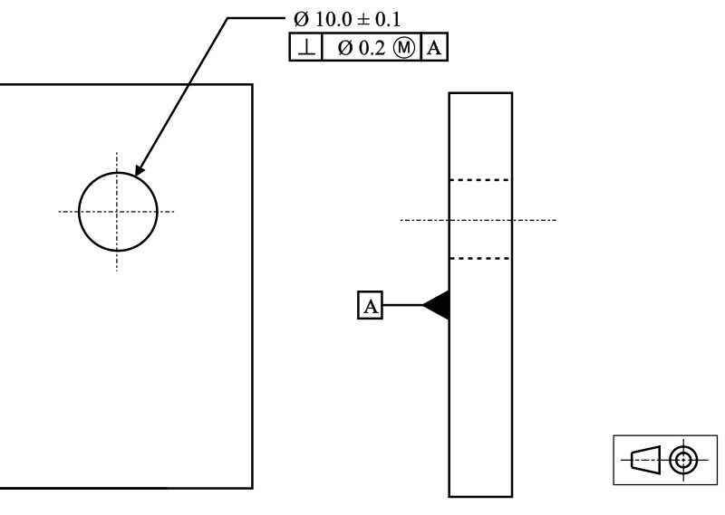
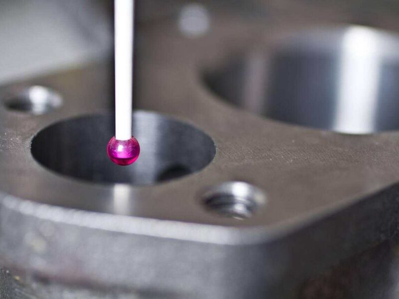
Tight tolerances will add to inspection and adjustment times. Features that have to mate with other components often require additional polishing and CMM verification.
Critical features are often designed steel-safe to allow material removal during mold correction. The method enables later removal of material for dimensional adjustments.
Quality of prototype tooling: What factors can affect it?
Tool quality affects dimensional accuracy, cycle stability, and surface repeatability. It depends on material, machining precision, and surface treatment, which control strength.
Surface Finish Depends on Tool Material
Machining behavior, surface replication, and mold life are directly affected by the hardness and polishability of tool materials. The steel, which machines more slowly than the aluminum but wears longer, maintains cutting edge integrity and dimensional stability over higher shot counts.
Composite tooling materials have a limited life span, which makes them only suitable for low-shot validation and early concept testing. They are only helpful in verifying basic concepts.
Better Material Gives Better Mold Finishes
Stable, fine-grain materials are required for high gloss and optical finishes. Stainless steel and high-grade aluminum have a stable microstructure and consistent machinability that make polishing easier and produce better surface finishes.
In porous or inconsistent materials, surface finish is limited due to the presence of micro porosity and non-uniform structure, which retain tool marks and reduce polishability. It can influence the uniformity of texture and cosmetic quality.
Machine Performance
Tool quality is determined by machine rigidity and spindle accuracy, which directly affect tool deflection and cavity dimensional error during the machining process. Good fixturing and thermal stability will minimize warpage, taper, mismatch, and surface marking on machined mold features.
A well-maintained CNC machine will generate more precise cavities. This enhances part-to-part consistency at T0 and T1 trials and minimizes corrective adjustments during mold sampling.
Tool Steel Grade Selection
The grade of tool steel directly relates to mold life, machining time, and the total cost. Faster machining with softer materials, but they wear faster in use.
The P20 is often used for prototype tooling because it machines well and has good strength. H13 is chosen for the higher demands on wear resistance and thermal strength. Material selection affects project longevity, manufacturing stability, and tooling cost.
Parting Line and Mold Alignment
Parting line quality is directly related to the look of parts and the consistency of edges. Accurate mold alignment is critical for correct part geometry and stable production results. Misalignment can lead to flash along edges and poor surface definition.
Also, ejector alignment is a big factor for smooth part release. Trial assembly checks alignment before production runs.
Mold Coatings
Mold coatings can improve tool life and surface performance over many cycles. They decrease wear and help maintain the surface quality uniformity. Typical coatings include nitriding and PVD treatments.
The coatings improve the resistance to abrasion and the degradation of the surface.
Common Materials Used in Prototype Tooling
The choice of material is influenced by the production volume, the abrasiveness of the resin, and the surface requirements. Engineers weigh the cost and durability of machining speed.
| Material | Typical Tool Life | Main Advantages | Common Uses |
| Aluminum 7075 | 1,000-10,000 shots | Fast machining and low cost | Design validation and pilot runs |
| P20 Steel | 10,000-100,000 shots | Good wear resistance | Extended pilot production |
| Stainless Steel | 20,000+ shots | Corrosion resistance | PVC and optical parts |
| Epoxy Composite | 10-500 shots | Very low cost | Concept verification |
| Kirksite | 500-5,000 shots | Stable and easy to form | Thermoforming tools |
Are There Alternatives to Prototype Tooling?
Several tooling methods are available for product development. The methods differ regarding their cost, durability, and capacity for production.
Prototype Tooling Vs Soft Tooling
Prototype tooling employs aluminum or soft steel for greater strength, dimensional control, and limited production. It allows for functional testing, tighter tolerances, and higher repeatability before full production tooling.
Low volumes, concept validation, and quick design changes are addressed by soft tooling using silicone or epoxy. The advantages are cheap and rapid iteration. But it isn’t capable of tight tolerances or long runs.
Prototype Tooling vs. Hard Tooling
Prototype tooling is made of aluminum or soft steel for speed and cost savings. It is not intended for long production runs and is mainly used for testing and validation before final investment in tooling.
Hard tooling is for large volume production and uses hardened steel. It has high wear resistance, dimensional stability, and repeatable performance over thousands of cycles.
Prototype Tooling Vs. Direct Tooling
Prototype tooling is used to produce low volumes of parts for testing before full production. It can employ direct or semi-direct methods to validate part fit, function, and molding performance at a reduced cost.
Direct tooling is the direct machining of the mold cavity via CNC or Additive manufacturing without the use of any intermediate steps. It is used for fast iteration and early-stage design validation as it reduces lead time and tooling cost.
Prototype Tooling Vs. Indirect Tooling
The prototype tooling can be used for direct and indirect manufacturing processes. Selection is based on cost goals, part complexity, and delivery time constraints. This flexibility allows for the balancing of fast delivery, tooling costs, and design requirements in early-stage development.
Indirect tooling first creates a pattern or insert, then uses it to produce the final mold. This process is also feasible for more complex geometries, but it needs more process steps and time.
Benefits of Rapid Prototype Tooling
Prototype tooling reduces risk in development and yields accurate parts early in the design process.
Reduces upfront tooling costs
Prototype molds are cheaper to make and use less material. This reduces the up-front cost and lets teams test designs before buying production tooling.
Allows Quicker Design Modifications
Soft steel and aluminium are easier to work with. Engineers can change dimensions, add inserts, and change critical features without having to rebuild the whole mold.
Helps Test Components Before Mass Production
Prototype tooling is produced using production-grade resins. This allows realistic testing of strength, thermal behaviour, fit of assembly, and compliance with regulations.
Speeds up product development decisions
Teams get molded parts right quicker. Measured results speed up design approvals and reduce uncertainty before production.
De-Merits of Prototype Tooling
Prototype tooling is often faster and cheaper, but it does have some limitations.
- The tool life is short, especially with abrasive resins and high temperatures.
- Cooling systems are often sub-optimal, which leads to increased cycle times.
- Surface textures may also be more limited than with hardened steel moulds.
- Part costs at higher volumes may be greater than the costs for production tooling.
- For tight tolerances, adjustments may be needed more often as the tool wears down.
Prototype tooling applications
Prototype tooling is used by many engineers in various industries to create parts that are production-ready in a short time.
Automotive
The components are tested in realistic conditions. The vibration behavior, the structural strength, and the heat resistance are examined. Design problems and verification of assembly fit are identified before mass production.
Healthcare
Functional performance and safety tests are performed, along with sealing and fluid control performance verification. Before final production, dimensional accuracy is verified to reduce development risk before approval.
Consumer Electronics
Product fit, form, appearance, housings, buttons, and assembly alignments are evaluated. Surface finish and cosmetic quality are checked to verify proper assembly.
Industrial Equipment
Structural fit is verified under actual operating conditions. Durability, strength, and mounting accuracy are checked before advancing the early development of enclosures and protective parts.
Defense & Aerospace
Prototype tooling helps verify dimensional accuracy, material performance, and assembly fit before production. It is also used to produce qualification parts for testing and approval before full-scale manufacturing.
Premium Parts: Best Tooling Supplier in China
We provide prototype tooling and low-volume injection molding for testing parts before mass production. CAD alone cannot confirm real molding behavior, so physical validation is required.
Our engineers review CAD models before tooling starts. We check wall thickness, sharp corners, tight tolerances, and gate position because it affects filling, shrinkage, and part quality.
Prototype molds are built in aluminum or steel, based on the project stage. Aluminum supports early designs with possible changes. Steel is used for stable designs and longer runs. Material selection also depends on the plastic type to avoid wear and defects.
During sampling, we evaluate flow balance, warpage, and ejection marks. Adjustments are made when needed to improve part quality and stability.
Conclusion:
Prototyping tooling enables engineers to quickly produce working parts with less initial investment. This enables design validation, material testing, and pilot production before full-scale tooling commitment. By using the right tool material and designing the mold correctly, teams can reduce risk during development and get the product to market faster.
When supported with proper engineering, prototype tooling can be a valuable intermediate step between concept development and production manufacturing.
FAQs
Can Prototype Tooling Use Production-Grade Plastics?
Engineering can use thermoplastics such as ABS, PC, nylon, POM, and glass-filled materials. This allows engineers to evaluate the mechanical properties, dimensional stability, and assembly performance in realistic manufacturing conditions.
How Quickly Can Prototype Tooling Be Produced?
Prototype tooling is typically completed in one to four weeks, depending on mold complexity, tool material, and finish requirements. Simple aluminum molds can be completed faster, but tools with more demanding requirements, close tolerances, and polished cavities require more time.
What are the typical materials for prototype tooling?
P20 steel and Aluminum 7075 are the most commonly used materials. Aluminum machines faster and costs less. P20 Steel gives more wear resistance for higher shot volumes and abrasive resins.