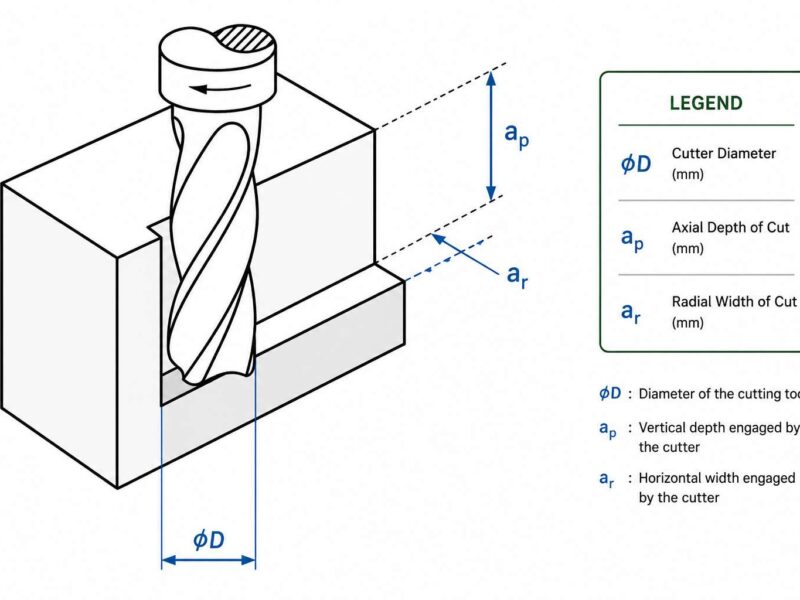
CNC-machined parts are often sharp-edged, which can cause problems during assembly, increase handling risks, and lead to early wear. They also increase stress concentrations at the corners, which reduces the component’s reliability under load.
There are two popular edge features used to ease sharp edges in CNC machining: chamfers and bevelled edges. Both cut material from the edges, but with different geometries and engineering requirements.
A chamfer is usually a small, flat, angled surface on an edge. A bevel is a larger-angle face, often taking up a larger portion of the part. Both processes are directly applied to CAD models and then fabricated by CNC machining with the use of controlled tools. At Premium Parts, our engineers apply chamfers and bevels based on the part’s functional and manufacturing requirements to improve assembly fit, protect edges from damage, and enhance overall component performance.
This article covers chamfer vs bevel design logic, production methods, and selection guidelines from an engineering and manufacturing point of view.
What is a Chamfer Edge?
A chamfer edge is an inclined plane surface created by removing a sharp corner of a part. It replaces a 90-degree edge with a controlled slope, usually at a fixed angle such as 45 degrees. Chamfers are used in CNC machining to protect edges from damage during handling and assembly. They also help in guiding the components during fit-up operations, especially in mechanical assemblies.
In designs, chamfers are used to reduce the stress concentration in the sharp transitions. This helps to improve the durability of parts exposed to cyclic loads. Typically, the chamfering is applied to internal holes and external edges depending on functional requirements.
How to Create a Chamfer in CAD?
In most CAD software, chamfers are created using a dedicated chamfer feature. The process typically involves the following steps:
- Identify the target edge geometry: Select the edges that require chamfering based on the part drawing and functional requirements. Chamfers are commonly added to external edges, hole entrances, and mating surfaces where edge preparation is required.
- Define the chamfer parameters: Specify the chamfer using a distance, an angle, or a distance-and-angle combination. These parameters determine the final edge geometry and must match the dimensions shown on the engineering drawing.
- Generate the chamfer feature: The CAD system recalculates the solid model by removing material along the selected edge and creating the specified angled surface. This updates the part geometry while maintaining the defined dimensional relationships.
- Transfer geometry for CNC machining: The completed CAD model is imported into CAM software. Here, the chamfer dimensions are used to select the appropriate cutting tool, generate the machining toolpath, and define machining operations. Well-defined chamfer features also simplify dimensional inspection and help ensure the machined part meets drawing requirements.
Why Do You Need a Chamfer?
A chamfer is added when a sharp edge may cause problems during machining, assembly, or handling. Instead of leaving a square corner, a small angled edge makes the part easier to use and manufacture.
Here are the most common reasons to use a chamfer:
- Makes assembly easier: A chamfer helps guide shafts, pins, bearings, and other mating parts into position instead of catching on a sharp edge.
- Removes burrs: After drilling or milling, small burrs often remain on the edge. A chamfer removes them and leaves a cleaner finish.
- Removes sharp corners: Sharp edges can damage nearby parts or make handling unsafe. A chamfer creates a smoother edge.
- Provides clearance: In some assemblies, a square corner can interfere with another part. A chamfer creates the extra space needed for a proper fit.
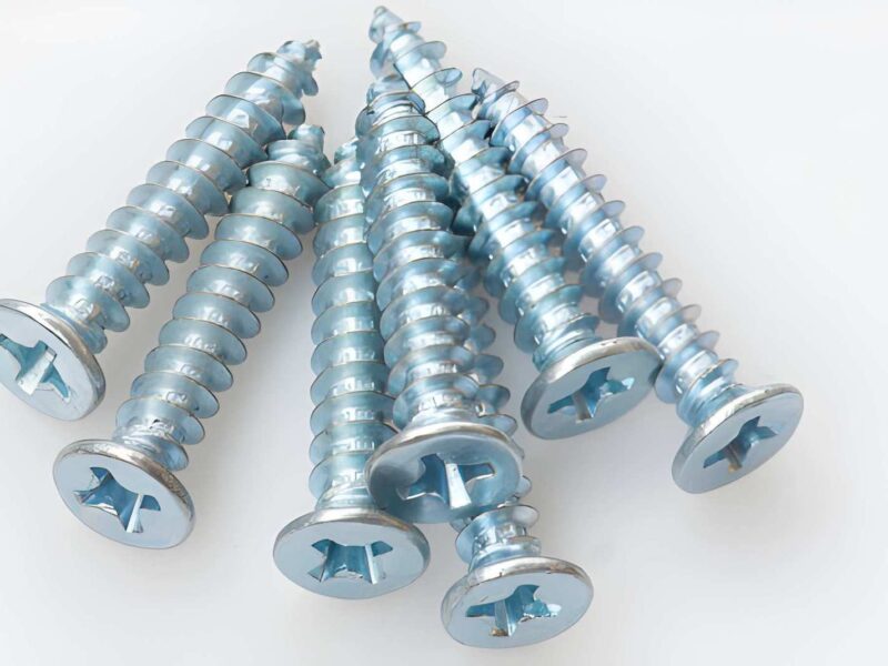
- Seats countersunk screws: Countersunk fasteners require a chamfer so the screw head sits flush with the surface.
- Improves finishing: Surface treatments such as anodizing, plating, or painting usually produce a more even result on chamfered edges than on sharp corners.
In most CNC parts, a chamfer is added because it solves a manufacturing or assembly requirement, not simply to change the appearance of the edge.
When Not to Use Chamfers?
- Avoid chamfers on gasket faces, O-ring sealing surfaces, datum features, and bearing shoulders because they reduce the required contact area.
- Do not apply chamfers to sealing faces, press-fit diameters, or locating shoulders, as these features rely on full edge contact.
- Chamfers are not recommended for sealing surfaces, datum edges, bearing seats, or press-fit features because edge removal can affect part function.
- Keep sealing faces, locating shoulders, and press-fit features square to maintain full contact and dimensional accuracy.
- Leave functional locating and sealing edges unchamfered to preserve proper contact, positioning, and fit.
Manufacturing Considerations:
Check tool access, use dimensions that are compatible with standard cutter sizes, and account for the internal corner radii left by end mills.
Functions of a Chamfer (Advantages)
- Chamfers improve component safety by removing sharp edges that can cause injury during handling.
- They also reduce surface damage during assembly. They help line up mating parts, guiding edges into place. This reduces the assembly effort and raises the production efficiency.
- Chamfers also minimise burrs after machining. This reduces the need for secondary finishing steps.
- In machine design, chamfers slightly reduce the stress concentration at corners and improve the fatigue performance under dynamic loading.
What Are The Types Of Chamfered Edge?
Classification of chamfers based on geometry and application is presented.
Chamfer by Distance & Angle (Custom Angle)
This type is defined by a specific distance and a chosen angle, such as 30 or 60 degrees. Engineers deploy it when they need controlled alignment or precise mating of parts. It is common in assemblies where the insertion is guided or the clearance is controlled.
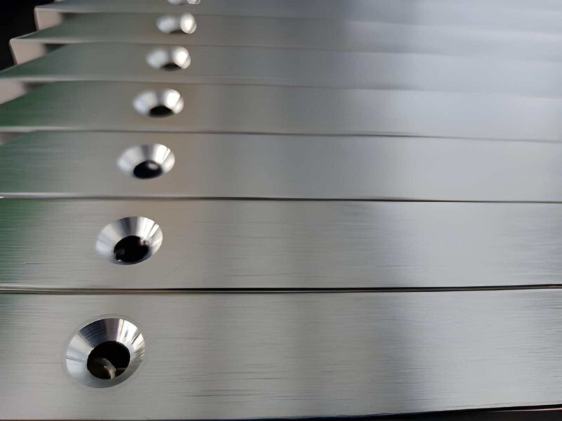
Hole Edge Chamfer (Lead-In Chamfer)
This chamfer is used at the entry of drilled or threaded holes. It guides fasteners, minimises edge damage, and preserves threads during insertion. On drawings for threaded or locating features, it is often called C1.0 by 45 degrees.
End Face Chamfer
End face chamfer is a chamfer around the end of shafts, tubes, or circular components. It removes sharp edges to improve safety and fit for assembly. It also reduces wear on rotating parts and is often used alongside fillets to improve edge durability.
Two-Distance Chamfer (Asymmetrical Chamfer)
An asymmetric chamfer has unequal material removal on the two adjacent edges, resulting in a non-uniform angle. It is used where space is limited on one side or when directional force control is needed during assembly. This type is often used on special mechanical designs.
Standard Chamfer (45° Equal Distance)
This is the most common type of chamfer in CNC machining. It cuts evenly on both adjoining surfaces, usually at 45°. It is easy to machine and very consistent. This design is commonly used for brackets, blocks, and general mechanical components.
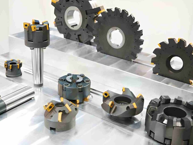
Machining Techniques for Chamfer Cuts Production
The most common way to produce chamfer cuts is by CNC milling. It enables precise control over the chamfer size and angle. Depending on the part geometry, end mills, chamfer mills, or spot drills are used by engineers.
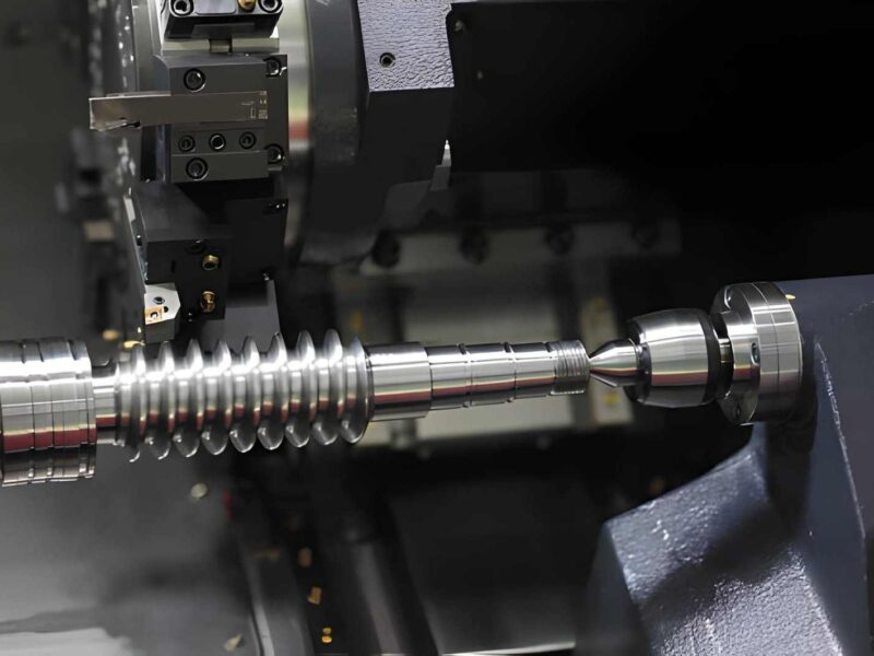
CNC turning produces chamfers on cylindrical components. The lathe tool is moved at a programmed angle to create chamfered edges and assembly lead-ins.
Small chamfers can also be produced by drilling operations. Holes are usually started with countersinking and spot drilling.
Grinding is used when close tolerances and fine surface finishes are required. It is typical of hard materials and precision components.
Chamfering on complex surfaces by multi-axis machining. It allows precise edge processing on inclined and curved surfaces.
When Should You Avoid Chamfering a Part?
Chamfers are not appropriate when a smooth stress distribution is required. In these cases, fillets are better because they have curved transitions. Do not use on sealing surfaces where full contact is required. Any break in surface continuity may influence sealing performance.
Chamfers are also less effective in high-load fatigue zones where stress concentration must be minimised.
Typical Chamfering Problems and Their Solutions
Chamfering is a simple operation, but setup and tooling errors can influence edge size, angle accuracy, and surface finish. Here are the most common chamfering problems and practical solutions used in CNC machining.
Inconsistent chamfer depth and width
The chamfer size may change along the edge when the workpiece is not flat, the tool deflects, or the Z axis is miscalibrated. This results in sections that are either too shallow or too deep. Fix this by leveling the workpiece, reducing the feed and depth of cut, and recalibrating the machine axis.
Chatter (Vibration) and Poor Surface Finish
Chatter creates a rough or wavy chamfer surface. It is usually caused by excessive tool stick-out, unstable cutting conditions, or spindle resonance. Improve the surface finish by reducing the tool overhang, reducing the spindle speed, and optimizing the feed per tooth.
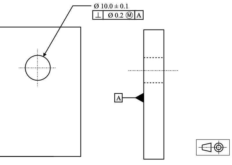
Poor Perpendicularity/Oblong Holes
If the tool is not at right angles to the surface, the chamfers on the hole become uneven. This can prevent the screws or bolts from seating flush. Hold tools securely and use rigid CNC setups to achieve 90° accuracy.
Clogging and Overheating of Chips
Packed chips increase the cutting temperature and tool wear. This is common when the coolant flow is not enough, or the flute space is too small. Move chips and control heat using effective coolant delivery and cutters with larger flute volumes.
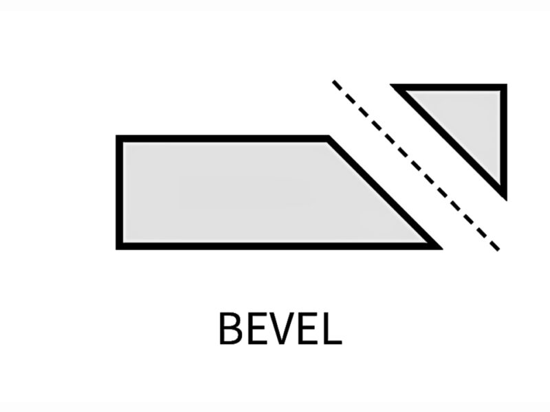
What is a Bevel Edge?
A bevel edge is an angled surface, typically cut at 30° to 45° relative to the part face, although other angles are used based on design requirements. Unlike a chamfer, a bevel usually extends over a larger area and is primarily used to prepare parts for welding or fabrication.
The angled edge creates space for deeper weld penetration and increases the weld cross-section, helping produce stronger and more reliable joints. Bevel angles are typically specified according to material thickness, joint design, and applicable welding standards.
CAD Bevel Edge Creation – How To Do It?
In CAD, you can create bevels by selecting edges and entering the angle and depth. The software then creates the geometry from these inputs.
Thus, the design is ready for machining and meets the requirements of welding. A good bevel design is important in fabrication because it has a direct effect on the quality of the weld and structural integrity.
Common Beveling Problems And Their Solutions
There are some machining and tooling parameters that can affect the bevel accuracy and final part quality.
Welding Fit-Up and Alignment Problems
A slight change in the angle of the bevel during welding can result in root gaps and misalignment. This is particularly important in thick sections where close tolerances must be maintained.
Deflection of Cutting Tool
The tool may deflect when making deep, long bevel cuts, resulting in uneven bevel width along the edge. Accuracy is assured through rigid tooling and optimized cutting parameters.
Thermal Expansion Due to Machining
Constant cutting creates heat. This can cause thin sections to expand a little bit and change the bevel angle slightly as it cools. Reduced by using the proper coolant and maintaining cutting conditions.
Tool Wear & Profile Deviations
As the cutting edge wears, the bevel can become rounded rather than a sharp, consistent angle. Tools must be regularly checked and replaced to maintain the quality of the bevel.
Common Bevel Types
Several types of bevels are available, each one for specific machining, assembly, and welding requirements.
Single bevel/plain
A plain bevel is a one-angle cut on one edge. Used for weld prep, basic assembly, and edge removal. This is the simplest and most common of the bevels in machine work.
Double Bevel (V bevel)
Double bevel cuts a V shape on either side of an edge. It is used in welding to increase the penetration and strength of joints. It keeps the symmetry of the structural joints well.
J-Prep Bevel
A J-prep bevel is not straight but is curved into a J-shape. Used in pipe and heavy-duty welding applications. It improves the penetration and reliability of the weld joint under high pressure.
Compound Bevels
A compound bevel is an edge with more than one bevel angle. It is used for precision machining and complex assemblies. It ensures a proper fit where normal bevels do not.
Radiused Bevel
A bevel that has a curve to the edge transition is called a radiused bevel. It reduces stress concentration in critical areas for parts subjected to cyclic or dynamic stresses.
Knife Edge Bevels
A knife-edge bevel is a steep, sharp angle that will cut well. For use on knives and cutting instruments. Some applications enhance penetration and cutting ability.
| Type of Bevel | Form / Geometry | Primary Purpose | Typical Applications | Key Benefits |
| Plain / Single Bevel | One flat, angled surface | Weld prep, Assembly lead-in, Edge breaking | Welded joints, Sheet metal, CNC-machined parts | Easy and inexpensive |
| Double Bevel (V-Bevel) | V-shaped angles on both sides | Enhance weld penetration and symmetry | Thick plates, structural weldments | Proper joint geometry |
| J-Prep Bevel | Curved J-shaped profile | Decrease weld volume | Pipes, pressure tanks | Less filler and less welding time |
| Compound Bevel | Two or more angles | Design intricate fits and clearances | Precision builds | Supports specialized geometry |
| Radiused Bevel | Angled edge blended with a radius | Stress concentration reduction | Fatigue load components | Increases durability |
| Knife Edge Bevel | Sharp edge from steep taper | Maximize cutting performance | Blades, cutting tools | Creates a sharp edge |
Machining Techniques for Bevel Cuts
The following machining methods are commonly used to produce bevels, depending on the part geometry, material, and design requirements:
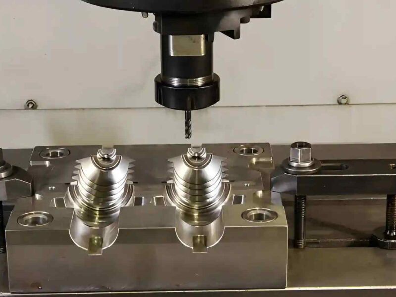
- CNC Milling
- Multi-Axis CNC Machining (4-axis and 5-axis)
- Surface Grinding
- Cylindrical Grinding
- Angle Milling
- Abrasive Cutting and Grinding
- Flame or Plasma Bevel Cutting (for heavy fabrication)
- Laser Bevel Cutting
- Waterjet Bevel Cutting
Applications of Bevel
Bevels are mainly used to prepare steel structures and heavy engineering components for welding. They give better weld penetration, which increases the strength of the joint and its reliability under load.
Bevels are also used in pipelines and pressure vessels where strong, leak-free joints are needed. Structural fabricating uses bevels to distribute mechanical stress on the welded joints.
When Should You Not Bevel A Part?
Tight assemblies with limited space are not recommended for bevels. They require more geometry, which can be difficult to fit into tight designs. They are also not necessary for cosmetic parts where the edge appearance is more important than structural strength.
The bevels require machining effort but are not functional if welding is not part of the manufacturing process.
Chamfer vs Bevel: What’s the Difference?
Both chamfers and bevels remove material from a part edge by creating an angled surface. The main difference lies in their engineering purpose. Chamfers are typically used to improve assembly, remove sharp edges, and protect machined features, while bevels are designed for weld preparation, structural joints, and applications that require a larger angled surface.
Geometry and Edge Size
A chamfer is a small edge break, most commonly machined at 45°, with dimensions defined by a distance or distance-and-angle callout. It removes only a small amount of material from the corner.
A bevel extends across a larger portion of the workpiece and may use a wide range of angles, such as 30°, 37.5°, 45°, or 60°, depending on the design or welding specification.
Manufacturing Requirements
Chamfers are easy to machine using standard chamfer mills, countersinks, end mills, or turning tools. They normally require only a single machining operation.
Bevels often require dedicated tool angles, multi-axis machining, or specialized cutting processes such as laser, plasma, or grinding, especially on thick plates or complex components.
Functional Purpose
Chamfers improve assembly by guiding mating parts, removing burrs, protecting edges from damage, and reducing handling hazards.
Bevels increase the available joint area for welding, create cutting edges, or provide clearance for structural assemblies where a larger angled surface is required.
Typical Applications
Chamfers are commonly applied to holes, shafts, brackets, housings, and general machined components.
Bevels are widely used on structural steel, pressure vessels, pipelines, cutting tools, and heavy fabricated parts before welding.
Technical Comparison: Chamfer vs Bevel
| Parameter | Chamfer | Bevel |
|---|---|---|
| Primary purpose | Edge finishing and assembly | Weld preparation and structural joints |
| Typical angle | Usually 45° | 20°–60° or as specified |
| Material removal | Small localized edge break | Larger angled surface |
| Geometry size | Short edge feature | Extends over a larger face |
| Machining methods | CNC milling, turning, countersinking, grinding | CNC milling, multi-axis machining, grinding, laser, plasma, waterjet |
| CAD definition | Distance, angle, or distance × distance | Angle and bevel depth or width |
| Inspection focus | Chamfer size and angle | Bevel angle, root face, bevel depth, and profile |
| Common standards | General machining drawings (e.g., C1 × 45°) | Welding and fabrication standards |
| Typical applications | Holes, shafts, housings, mounting features | Welded plates, pipes, pressure vessels, and cutting tools |
| Manufacturing complexity | Low | Moderate to high |
Summary
Chamfers and bevels are both used in CNC machining to improve edge condition, but for different functional and manufacturing purposes. Bevels for weld strength and structural integrity, chamfers are mainly used for assembly, safety, and cost-effective production. In each case, the choice of the feature is governed by design intent, loading conditions, and manufacturing constraints. Getting engineers to robust, efficient, and production-ready designs requires understanding how to handle these edges correctly.
Get Expert CNC Machining Support from Premium Parts
Selecting the right edge feature is only one part of a successful design. At Premium Parts, our engineering team reviews your CAD model to recommend the most suitable machining approach based on the part geometry, functional requirements, material, and production volume.
We help optimize features such as chamfers, bevels, holes, and other machined details to improve manufacturability, reduce unnecessary machining time, and avoid costly design revisions. Our team also checks tooling access, tolerance requirements, and machining feasibility before production begins.
With advanced CNC machining capabilities, tight quality control, and support from prototype to production, we deliver precision parts that meet your design requirements while keeping lead times and manufacturing costs under control.
Upload your CAD file today to receive a detailed manufacturability review, competitive quotation, and expert recommendations for your next CNC machining project.
FAQs
What is Chamfering in Engineering?
Chamfering is the process of beveling sharp edges to improve safety and ease of assembly. This makes it safer and easier to assemble. It also results in a decrease of burrs formation during machining.
What Are the Advantages of Bevels in Engineering Designs?
Bevels increase the area of contact in the joint and therefore the strength of the weld. They also enhance the transfer of loads in the structural assembly.
How Can Beveling Improve Weldability and Joint Integrity?
Beveling allows the weld to penetrate further between the pieces. This leads to stronger, more reliable welded joints under load conditions.