Every cutting process leaves a kerf, removing a swath of material along the cut path. The width and shape of this swath determine how closely the final part dimensions match the drawn dimensions. A laser produces a kerf narrower than a sheet of paper, while an oxy-fuel torch on thick plate can remove several millimeters.
If cut paths are not compensated for this removed material, holes will be larger than drawn, external profiles will be smaller than drawn, and resulting mating parts will not fit together. In addition, kerf affects edge squareness, minimum feature sizes, and the nesting density of parts on a single sheet.
Choosing the appropriate cutting process for a part begins with understanding the kerfs produced by each process.
Introduction: What Is Cutting Kerf?
Cutting kerf is the width of material cut away by a cutting tool or a beam when it cuts through the workpiece. It is the distance between the two sides of the cut. A kerf is present in any kind of subtractive cutting process:
- Thermal processes (laser, plasma, oxy-fuel) melt, burn, or vaporize material, which is blown out of the kerf.
- High-velocity abrasive particles cause erosion of the target material in abrasive waterjet cutting.
- Electrical discharges remove material during wire EDM between the wire and the workpiece.
- In sawing and milling, the teeth or cutting edges remove material in the form of chips.
Kerf width is typically defined by the dimension of the cutting tool (beam spot, jet stream, wire, blade) along with the additional amount of material cut around it.
Kerf Width, Kerf Taper and Edge Geometry
Kerf is defined by more than one parameter. There are three terms used to compare cutting processes:
- Kerf width refers to the measured gap across the cut, generally measured at the top surface of the material.
- Kerf taper is defined as the difference between the kerf width at the top of the cut and at the bottom. In a V-shaped kerf, the taper has a larger kerf width at the top of the cut, while a reverse taper has a larger kerf width at the bottom of the cut. Kerf taper causes the edges of the specimen to be cut slightly out of square.
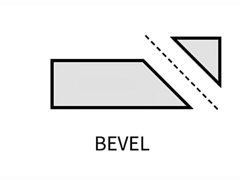
- Edge bevel is an angled edge characterized on one side of the cut, often seen in plasma cutting, where one side of the kerf is squared, and the other side is angled.
Even processes with a narrow kerf but high taper can result in poor accuracy on thick parts, so both width and taper need to be checked together.
Types of Cutting Kerf by Process
Each cutting process produces a kerf with a characteristic width, taper, and edge condition. The following are typical ranges and will vary with specific machine, settings, and material thickness.
1. Laser Cutting Kerf
A focused beam of laser melts or vaporizes the material, and assist gas (nitrogen, oxygen, or air) clears the molten metal from the cut.
- Typical dimensions on sheet metal: approximately 0.1 to 0.4 mm
- Taper: small on thin sheet, but increases on plate above about 10 mm.
- Edge condition: smooth edge with fine striations; there is a thin HAZ and possible dross on the bottom edge.
- Ideal application: Sheet metal components with small perforations, slots, and precise profile tolerances
2. Plasma Cutting Kerf
The high-temperature electrically conductive gas melts the metal, which is blown out by a high-velocity gas jet.
- A typical width of about 1.5-4 mm, depending on the current and nozzle size
- Taper is noticeable; high-definition plasma reduces taper.
- Edge condition: the swirling gas creates a square “good side” and a beveled “bad side”. However, the cut direction must be configured so that the part retains the square side.
- Most suitable for: medium to thick conductive metals with a priority on speed over fine detail.
3. Oxy-Fuel Cutting Kerf
Carbon steel is heated to ignition temperature by a preheat flame, and then pure oxygen is used as an oxidizer to burn the metal into oxide slag.
- Typical width: from 1.5 to 5 mm, depending on the plate thickness and the size of the tip.
- Taper: low if the tip is set correctly.
- Edge condition: a rougher surface with a wide heat-affected zone (HAZ) and slag on the bottom edge
- Optimally suitable for: thick carbon steel plate, unsuitable for stainless steel or aluminum.
4. Abrasive Waterjet Kerf
This process uses a water stream at approximately 3,500 to 6,000 bar to carry garnet abrasive that erodes the material.
- It generally varies from 0.8 to 1.2 mm in width. Pure water cutting (without abrasive) ranges from 0.1 to 0.4 mm for soft materials.
- Taper: V-taper observed at elevated cutting speeds; the use of 5-axis taper compensation heads addresses this issue.
- There is no Heat Affected Zone (HAZ) at the edge condition, and the surface roughness increases toward the bottom of thick sections.
- Optimal match for: heat-sensitive metals, composites, glass, stone, and thick aluminum
5. Wire EDM Kerf
Material is removed by controlled electrical discharges through the use of a thin brass or coated wire, which acts as the electrode, immersed in deionized water.
- Width is typically equal to the diameter of the wire plus a spark gap on each side. For a 0.25 mm wire, this results in an approximate width of 0.30 to 0.35 mm.
- Taper: close to zero, unless taper is requested.
- The edge condition exhibits a highly precise edge and features a thin recast layer.
- Best fit: hardened tool steel for punches, dies, and precision components with tolerances of approximately ±0.005 mm
6. Saw Blade Kerf
A band saw, or circular saw, cuts chips from the material with its teeth. To avoid the blade body rubbing, the teeth are bent outward slightly (referred to as “set”).
- Common dimensions: approximately 1 to 2 mm for band saws and 2 to 4 mm for circular saws
- Taper: none in a straight cut, but blade drift can wander on extended sections.
- Edges can have burrs on the exit side. The surface quality is dependent on the pitch of the tooth.
- Best fit: cutting bars, tubing, and profiles to size before machining
Kerf Comparison Summary
| Process | Typical kerf width (mm) | Taper | HAZ | Materials |
| Wire EDM | 0.30 to 0.35 | Near zero | Thin recast layer | Conductive metals |
| Laser | 0.1 to 0.4 | Low | Narrow | Most metals, some plastics |
| Abrasive waterjet | 0.8 to 1.2 | Medium (V-taper) | None | Almost any material |
| Saw blade | 1 to 4 | None | None | Metals, plastics, wood |
| Plasma | 1.5 to 4 | Medium, one beveled side | Medium | Conductive metals |
| Oxy-fuel | 1.5 to 5 | Low | Wide | Carbon steel only |
For help matching a part’s tolerance and material to the right cutting process, contact Premium Parts and share the drawing for a process review.
Factors That Change Kerf Width
Kerf is variable for a process. A machine may have different kerfs for different jobs for the following reasons:
- Material thickness: Thicker components require increased power and decreased speed, which increases kerf width and, as a result, increases taper.
- Cutting speed: If it’s too slow, the kerf becomes wider; if it’s too fast, tapering occurs, and the bottom remains uncut.
- Power or current: Increased laser power or plasma current increases kerf width.
- Nozzle, orifice, or wire size: The cut element determines the minimum possible kerf.
- Focus position and standoff height: An incorrectly set laser focus or torch height disperses the energy and enlarges the cut.
- Consumable erosion: Used plasma nozzles and waterjet focusing tubes enlarge as time passes, which increases kerf over the course of a production run.
- Lighter reflective metals such as aluminum and copper, as well as materials that do not melt uniformly, produce a less consistent kerf than mild steel.
Kerf Compensation in Design and CAM
Kerf compensation moves the cut path by half the width of the kerf to ensure the final edge is on the drawn line.
- Outer profiles: The path is set to the outside offset, making the piece true to size.
- Holes and internal cutouts: The path is offset inwards, preventing the holes from being oversized.
- Compensation on the machine: Many CNC controls support kerf compensation (G41/G42), which allows the operator to change the value as consumables wear, eliminating the need to re-enter the program.
- Part spacing in the sheet: a minimum distance equal to the kerf width plus some margin should be kept between nested parts to accommodate issues related to heat and edge finish.
- Mating features such as slots, tabs, and press-fit holes are designed based on the nominal dimensions rather than the actual process kerf and taper.
Contact Premium Parts to confirm kerf allowances for slot-and-tab assemblies and close-fit features before cutting begins.
Conclusion
The cutting kerf determines how much material each process removes and the overall accuracy of the part in relation to its print. Wire EDM and laser cutting offer the narrowest and most consistent cutting kerf, waterjet offers a mid-range cutting kerf without thermal stress, and plasma, oxy-fuel, and saw cutting all provide a wider kerf for thicker stock and faster production. Cutting kerf, taper, and edge bevel – all three must be considered together, as well as compensated for in the CAM tool path.
To get a quote on your design for cut parts using the most suitable process and required cutting kerf allowances, contact Premium Parts and submit your prints.