Thanks to years of innovation and development, metal 3D printing is quickly becoming a standard process in manufacturing. With additive manufacturing, many industry sectors can leverage the speed, cost-efficiency, and design edge of 3D printing to create a variety of components for end-use parts. 3D printing continues to offer exciting opportunities for next-gen parts that need to have great freedom of design, complex geometries, and high strength-to-weight ratios.
Additive manufacturing using metals also enhances supply chains, reduces process bottlenecks, and tailors production for specific turnkey purposes. As exciting as all of this may seem, it is essential to note that metal 3D printing comes with some constraints. For one, it is not as easy as 3D printing plastic parts. This is due to the level of difficulty in printing metal parts, the law of physics, the machining considerations, and more. Today’s blog will discuss metal 3D printing and provide simple design tips to incorporate for better metal 3D printed parts.
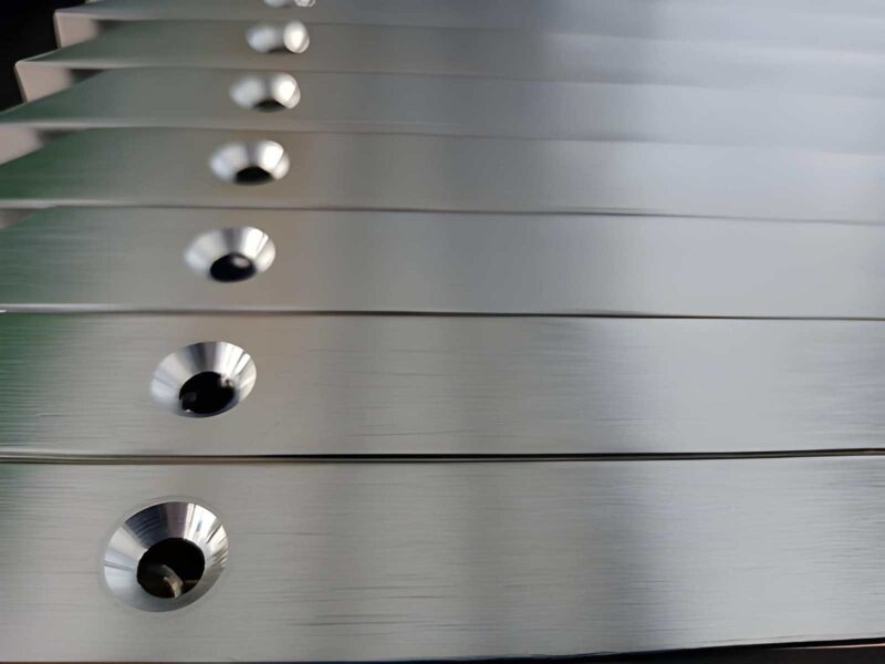
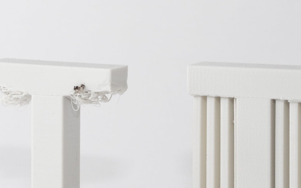
1. Manage the Wall Thickness in Your Design
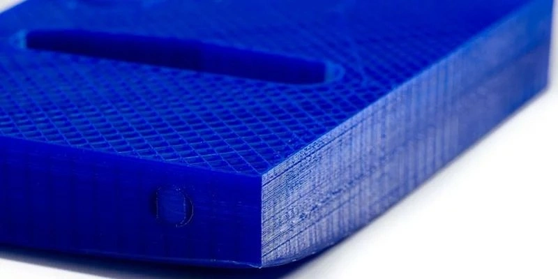 3D Printing Wall Thickness
Image Description: A close-up view of a 3D-printed part, showing its wall thickness.
We recommend keeping wall thickness and other features in the design no less than 0.5mm. This is because many processes in the production may cause the walls to begin to collapse under their own weight at dimensions thinner than half a millimeter. Although it is possible to run a thinner wall thickness, the rapid heating and cooling of the melting process during the metal 3D printing can cause these features to become distorted. Achieving thinner walls is also subject to printer orientation, material type, and other print parameters. To be safe, always strive to keep your walls no thinner than 0.5mm.
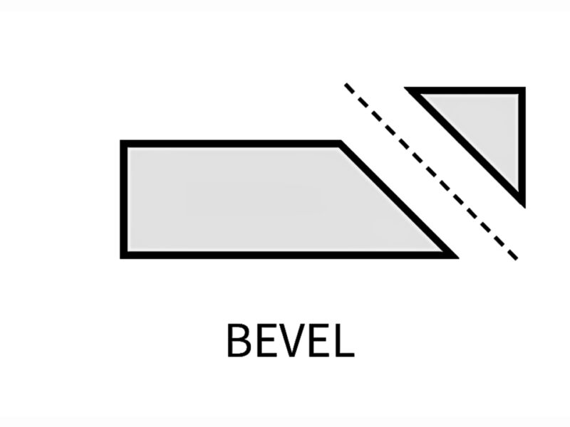
2. Minimize Overhangs
 3D Printing Overhangs
Image Description: This illustration shows two types of 3D printing overhangs.
Keep all overhangs lower than 0.5mm to prevent the collapse of the down surface area. When designing your part, keep all downward-facing features with a chamfered, concave, or convex geometry (and angle) to make them self-supporting. This angle (often 45 degrees to the horizontal surface) may also be reduced by maintaining optimal laser parameters during the printing operation. Overhangs that extend past 0.5mm will eventually lead to a breakdown in the build.
3. Gaps and Holes
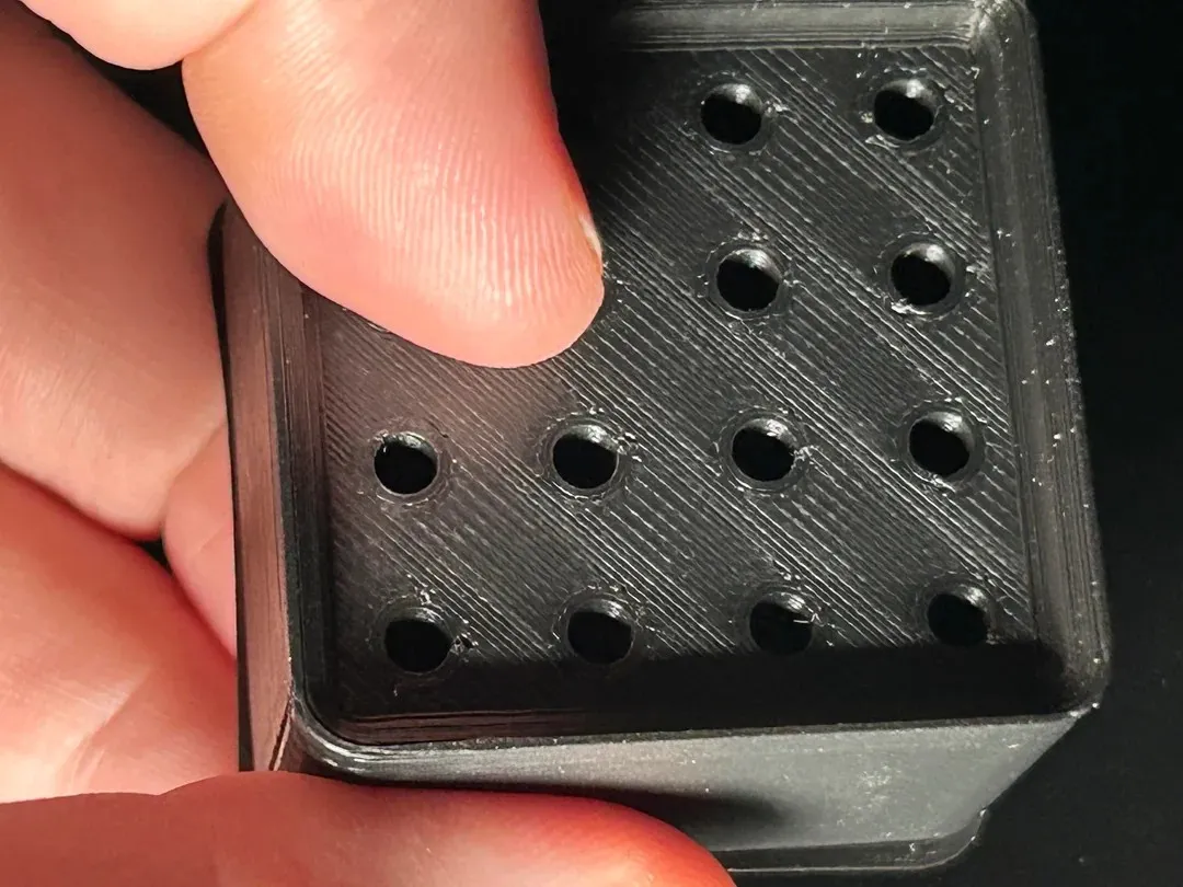 Gaps/Holes in the 3D Print walls
Image Description: A person holds a 3D-printed part in a close-up view, showing gaps and holes in the walls.
There is no fixed approach to gaps and holes. This is because many factors come into play here. These factors include the type of primer being used, the complexity of the design, geometry, and the nature of the metal used. Generally, avoid designing a hole or gap below 0.5mm to prevent the risk of either side merging and filling the hollow space. Escapes holes can be used to remove unmelted powder in metal 3D printed parts. If you have an escape hole, ensure that your bore diameter is no less than 2mm and no more than 5mm. You can also design more than one escape hole in your part to ease the removal of unmelted powder after printing. You will need some form of support structure to compensate for vertical or horizontal holes that need to be larger than 10mm in diameter.
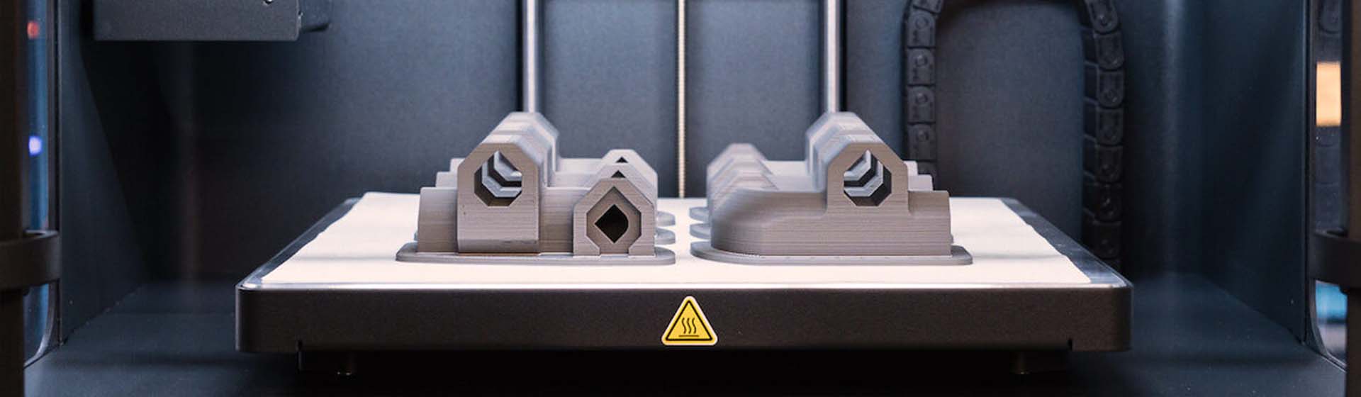
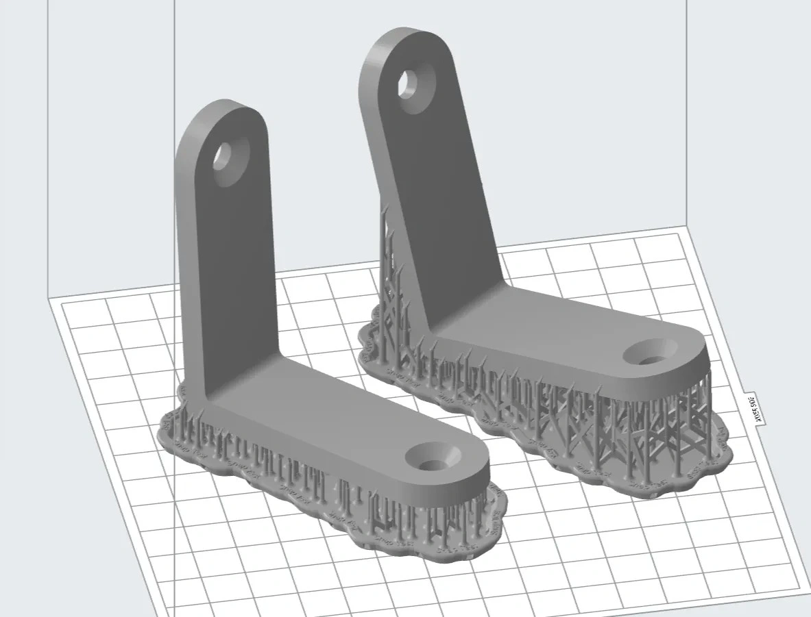
4. Support Structures and Unsupported Angles
 3D Printing Supports
Image Description: Simple view of 3D-printed supports.
Support structures are necessary for providing enforcement for the build and promoting heat dispersal during 3D printing. Any area in your design that is lower than 45 degrees from the horizontal plane will typically need support structures.
Self-supporting angles should be kept above 45 degrees to prevent collapse and failure due to excess gravity pull from below. This will also occur to any unsupported angles in the design that have been over-inclined from the vertical point.
5. Part Orientation
Part Build Orientation in 3D Printed Parts
Image Description: An Illustration showing part orientation in 3D Printing.
Consider beforehand how the printing orientation of your part may affect its physical and mechanical properties. As the printing orientation plane significantly affects the anisotropic characteristics of the build, you will need to factor in how the print should be produced relative to the force or pressure that each part of the product will be subjected to.
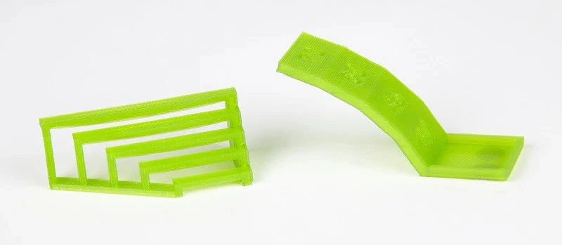
6. Consider Latticing Designs
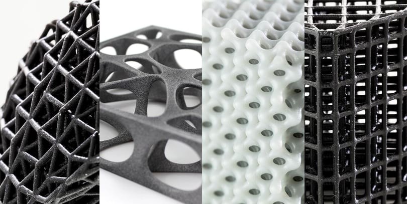 3D Printed Lattices
Image Description: Different Lattice Design in 3D Printing.
Consider the use of lattice structures to remove unwanted mass without compromising on strength in your part. Additive manufacturing, unlike CNC machining and injection molding, enables the creation of delicate, complex lattice designs that enhance the part’s strength while reducing the material mass required to solidify it. This is highly recommended in the design as lattices are a guaranteed way of adding more strength and incorporating visual appeal in your metal printed part.
Premium 3D Printing Services in China
As one of the top manufacturers in China, we encourage you to try out our high-quality online 3D printing service solutions and get underway with your first 3D project. Our engineers are available to help with a free quote and design evaluation. Depending on the nature of your project, you will typically receive your quote in a few hours, as well as some suggestions on how to enhance your end part. Premium Parts also provides stringent quality control evaluations and super-efficient logistics that guarantee that you receive your 3D printed objects, produced to specifications as desired, quickly, intact, functional, and most importantly, affordably.