Centerless Grinding is a type of precise cylindrical grinding that takes material off the outside diameter of a rotating workpiece without being mounted between centers or clamped in a chuck.
Rather than that, the workpiece actually sits on a work rest blade that is located between two wheels (a high-speed abrasive grinding wheel and a rubber-bonded regulating wheel), with the three-point contact arrangement causing the workpiece to rotate against the grinding wheel at a controlled feed rate and therefore, produce consistent removal of material, tight roundness tolerances (typical with ±0.0001 inches/±0.0025 mm). Surface finishes down to Ra 0.1 µm.
Because fixturing is not necessary for loading or unloading parts, the throughput rate achieved with centerless grinding cannot be achieved on conventional cylindrical grinders or CNC lathes. Therefore, centerless grinding serves as the backbone of high-volume production of round bars, shafts, and bearings in the aviation, automotive, and medical industries. So, let’s dive in and explore more about centerless grinding.
What Is Centerless Grinding and How Does It Work?
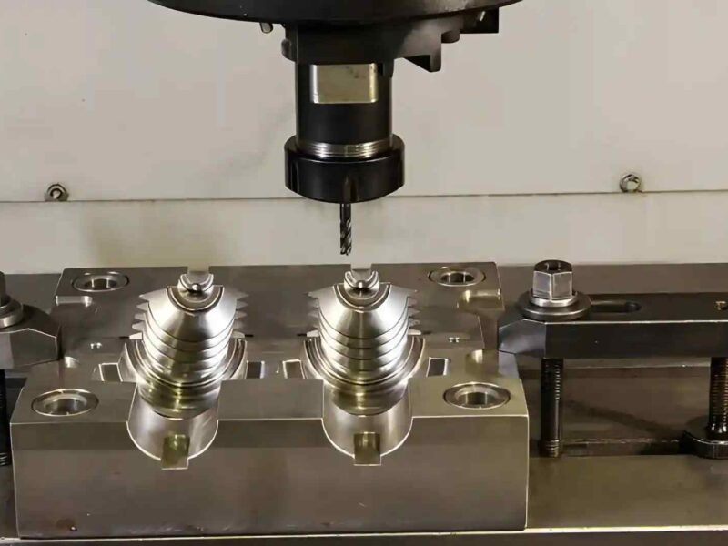
In centerless grinding, there are three main components involved in each cut: the grinding wheel, the regulating wheel, and the work rest blade. The grinding wheel (usually made of aluminum oxide, cubic boron nitride (CBN), or diamond) rotates at speeds between 25 and 60 m/s, removing material from the part. The regulating wheel (which is made of either rubber-bonded abrasive or rubber-bonded friction material) rotates in the same direction as the grinding wheel, but at a much lower speed (i.e., between 0.1 and 0.5 m/s) and controls both the workpiece’s rotational speed and also, in through-feed mode, its feed rate in the axial direction.
The work rest blade supports the workpiece from underneath and positions its centerline slightly above the centerline connecting the two wheel axes. The height above the centerline of the two wheels is critical because it has a self-rounding effect: any high point on the part’s surface will contact the grinding wheel with increased force, removing more material until the part is truly round. If the workpiece is located at or below the wheel centerline, the geometry will promote a polygonal shape (lobes) in the workpiece, permanently destroying its roundness.
The angle of the regulating wheel also has a major impact on axial thrust generation, tilting 1°-6° away from vertical. This axial thrust will drive the workpiece through the machine via through-feed operation.
Types of Centerless Grinding
Centerless grinding can be divided into three methods. The selection of the centerless grinding method depends on the workpiece geometry, batch size, and dimensional specifications. Each of the three major feed types is suited to a particular class of applications.
Through-Feed Centerless Grinding
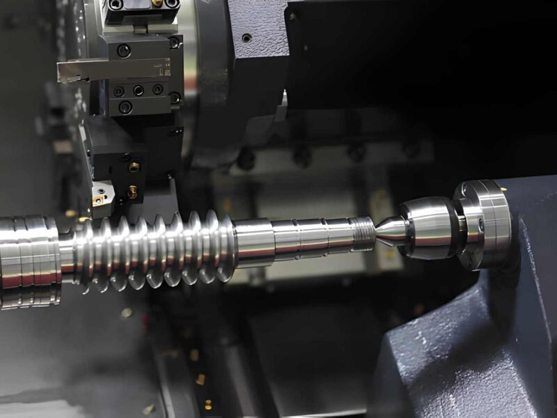
Through-feed grinding is when the workpiece enters at one end of the wheel gap, passes through the wheel set on the full width of both wheels (the regulating wheel’s angle creates the axial movement of the workpiece), and exits on the other side of the wheel set after grinding.
Continuous feeding of workpieces occurs without interruption while simultaneously achieving very high production rates (generally 100 to 500+ workpieces per minute on small-diameter bar stock).
Through-feed grinding can only be used on workpieces with a tubular cross-section and a uniform diameter throughout their length. Examples of parts suitable for through-feed grinding include round bars, pins, needle rollers, and actuator rods for hydraulic cylinders. Parts that have shoulder(s), taper(s), or change in diameter(s) disqualify them from being processed by through-feed grinding.
In-Feed (Plunge) Centerless Grinding
Centerless Grinding. In-feed Grinding is also known as Plunge Grinding. The workpiece can be loaded into the wheel gap (at a fixed axial position) using manual or robotic loading.
The grinding wheel advances radially into the workpiece until the programmed stock removal is completed. There is no axial movement of the workpiece; instead, both grinding wheels create a specific grinding zone as the workpiece rotates in place.
The in-feed method can process complex profiles, such as stepped diameters, shoulders, and formed shapes, that cannot be processed with through-feed grinding. In-feed centerless grinding is ideal for camshafts, valve stems with unique head geometry, and externally formed pistons.
A primary benefit of the in-feed process is that it produces accurate length tolerances because the end-stop holds the workpiece in a fixed position along the axial plane.
End-Feed Centerless Grinding
End-feed grinding is a method used to create a specific amount of relief with a dull tool. One can use this process by feeding the workpiece into the wheel at one end, grinding along the wheel’s face, and stopping at a predetermined point to set the workpiece’s axial length.
The working surfaces of both wheels will be designed and set up to match the taper of the workpiece produced by this process. The valve seat and the taper of roller bearings and conical pins would typically be produced by this method.
External vs. Internal Centerless Grinding
| Parameter | External Centerless Grinding | Internal Centerless Grinding |
| Grinding zone | Outside diameter (OD) | Inside diameter (ID) |
| Wheel configuration | Grinding wheel + regulating wheel + blade | 3 rollers: regulating, support, pressure |
| Workpiece support | Work rest blade | Outer surface of workpiece |
| Typical applications | Shafts, bars, rollers, tubes (OD) | Tube bores, ring IDs, bearing races (ID) |
| Achievable roundness | ±0.0025 mm | ±0.005 mm |
Key Components of a Centerless Grinding Machine
To properly set up and troubleshoot the machine, you must have a basic understanding of its parts, as each part directly affects the output dimensions.
Grinding Wheel
The grinding wheel is the principal cutting part of the centerless grinder. The cutting ability of the wheel is defined by the abrasive (Al₂O₃, CBN, diamond), the size of the grains (Grits from 46–220), the type of bond (vitrified, resinoid, rubber), and the grade of the wheel (hardness).
These variables directly affect the amount of material removed per minute, the surface finish, and the amount of heat generated during the process.
Regulating Wheel
The regulating wheel controls how fast the workpiece turns and how quickly it is fed in the axial direction in through-feed processes. The wheel’s tilt angle determines the workpiece’s rotation speed.
Typically, regulating wheels are rubber-bonded, providing high friction and a positive drive for the workpiece. If a regulating wheel is worn or glazed, slippage will occur, resulting in unpredictable roundness in the finished workpiece.
Work Rest Blade
This tool supports the workpiece between the grinding wheel and regulating wheel during the grinding process. The blade material (carbide vs. steel), the blade angle (standard 30° for most jobs), and the blade height relative to the wheel’s centerline all affect the workpiece’s self-rounding and chattering tendencies.
Wheel Dresser (Crush Roll or Diamond Dresser)
The wheel dresser (either a crush roll or a diamond dresser) will continuously or periodically sharpen and profile a grinding wheel. CNC-controlled dressers (currently standard on new centerless grinders) automatically maintain the geometry of the grinding wheel, which directly affects how each part is produced.
Machine Bed
The machine’s cast-iron or polymer-composite base provides vibration damping and thermal stability, enabling it to produce grinding with great accuracy. More recently, granitic machine beds have become popular in high-precision applications.
CNC Control Unit
The latest generation of centerless grinders incorporates CNC controls to enable servo-driven regulating wheel positioning, automatic in-process gauging, and adaptive feed control.
The CNC continuously adjusts the machine settings to keep the diameter within a given tolerance band, without requiring operator intervention.
Centerless Grinding: Critical Setup Parameters
The main ways operators can control the quality of their operations are through process tool setup variables. If process tool setup variables are not set correctly, there will be consistently observed defects that can be diagnosed.
| Setup Parameter | Effect on Process | Typical Range |
| Workpiece center height above wheel CL | Controls self-rounding vs. lobing tendency | 0.5 – 1.5× workpiece radius |
| Regulating wheel tilt angle | Controls axial feed rate in through-feed | 1° – 6° |
| Regulating wheel surface speed | Controls workpiece RPM (= regulating speed × wheel diameter / workpiece diameter) | 10 – 75 RPM workpiece |
| Grinding wheel surface speed | Controls material removal rate and surface finish | 25 – 60 m/s |
| Infeed rate (plunge grinding) | Controls stock removal rate and cycle time | 0.005 – 0.05 mm/rev |
| Coolant pressure and flow | Controls thermal load, wheel loading, and chip flush | 50 – 100 psi / high flow |
Common Defects and Root Causes
Mapping defects to their causes is a powerful tool that will significantly reduce setup times for new parts. Some examples include:
- Chatter Marks (Waviness on outer diameter): Work rest blade too low, grinding wheel too hard for the material, too much speed of wheel for the hardness of the part being ground.
- Lobing (Polygonal cross-section): Workpiece centerline is at or below wheel’s centerline, regulating wheel slipping, and regulating wheel is glazed.
- Taper (little variation in diameter along the length): Regulating wheel tilt angle is misaligned, and wheel faces are not parallel with one another.
- Burn Marks (Thermal discoloration): Insufficient flow or pressure of coolant, the grinding wheel is loaded or glazed, or the infeed rate is too aggressive for the material being ground.
- Poor Surface Finish: Coarse grit on the grinding wheel, excessive rotational speed of the workpiece, and the wheel requires dressing.
Materials Suited to Centerless Grinding
Generally, centerless grinding is available for many types of materials. However, proper wheel selection must match the workpiece material’s hardness, thermal conductivity, and chemical reactivity with the abrasives.
| Material | Recommended Abrasive | Wheel Bond | Special Considerations |
| Hardened steel (58 -65 HRC) | CBN | Vitrified | Through-spindle coolant; dress frequently |
| Stainless steel (304, 316) | Aluminum oxide (white) | Vitrified | Low grinding pressure; risk of work hardening |
| Titanium alloys | CBN or diamond | Resinoid | High coolant flow; avoid Al₂O₃ (chemical reactivity) |
| Cemented carbide | Diamond | Vitrified or metal bond | Very low MRR; tight spark-out passes |
| Aluminum alloys | Silicon carbide | Resinoid | Open the wheel structure to prevent loading |
| Engineering ceramics (Al₂O₃, SiC) | Diamond | Metal or vitrified | Brittle fracture risk; fine grit; slow infeed |
| Engineering plastics (PEEK, Nylon) | Silicon carbide | Resinoid | Minimal heat generation; air cooling preferred |
Advantages of Centerless Grinding
When it comes to producing parts efficiently, accurately, and in various shapes, there is no better process than centerless grinding. Here are several benefits that centerless grinding has to offer:
- No need for fixtures: With centerless grinding, using the self-supporting three-point contact, the setting of a chuck is eliminated. This allows for a much quicker changeover to another part than with a conventional center-type cylindrical grind.
- High production rates: Through-feed grinding allows one part after another to be ground in concert, for many smaller diameters of rods and pins; this has been seen at above 300 parts per minute.
- High roundness and surface finish values: The self-rounding feature of centerless grinding ensures that worn or imperfect stock can be corrected for out-of-roundness. Dimensionally good roundness of 0.0005 to 0.002 mm can be achieved; surface finishes on parts can reach Ra 0.2 to 0.4 µm for production.
- Rigid workpiece support: The work rest blade supports the workpiece continuously along its entire length, therefore preventing any deflection during the grinding operation. This allows one to grind through greater amounts of material than with conventional center-type grinding for the same slender parts.
- Wheel life is improved: The workpiece rotates independently of the wheel drive; therefore, the forces produced by the grinding action are much more evenly distributed across the wheel face, decreasing localized wheel wear.
- Automation compatibility: Modern centerless grinding cell setups are capable of unassisted formation of workpiece using robot part loading, in-process gauging with automatic size compensation of parts, and post-process sorting of parts, allowing the modern manufacturer to perform work non-stop.
Limitations of Centerless Grinding
Centerless grinding has significant limitations despite its productivity advantages.
- Unsuitable for interrupted or non-round profiles: Keyways, flats, or off-center features inhibit three-point seating on the work rest blade, creating an unstable condition for the workpiece.
- Difficult for short or wide parts: A workpiece with a length-to-diameter ratio of less than 0.5:1 will usually be unstable in the wheel gap and will be at risk of chattering or ejecting.
- No axial position reference (through-feed): Through-feed operations do not provide any form of length reference for the workpiece, making it impossible to reliably locate a hole, shoulder, or other length-based feature; therefore, in-feed or end-feed systems are required.
- Complex setups for small runs: Adjusting wheel gap, blade height, tilt angle, and dressing parameters to work with different diameter workpieces is labour-intensive and requires technical competence. Therefore, centreless grinding is cost-effective only for workpieces produced at medium-to-high production volumes.
Industrial Applications of Centerless Grinding
Centerless grinding is found in nearly every precision manufacturing sector today, which makes it easy to understand why many engineering drawings specify centerless grinding by name when they are developed. Some examples of this are included below:
Automotive: Crankshaft journals, transmission input and output shafts, fuel injector needles (0.001 mm roundness tolerance), piston pins, and valve stems.
Aerospace: Turbine blade roots, landing gear actuator rods, fastener shanks, and hydraulic valve spools all require tight diameter tolerances and traceability as per AS9100.
Medical Devices: Orthopedic implant rods (titanium and cobalt chrome), surgical instrument shafts, catheter guide wires, and dental drill shanks; traceability per ISO 13485 applies to all medical devices manufactured using centerless grinding.
Bearings: Inner races, outer races, needle rollers, and ball raceways are all produced in the bearing industry, which is one of the largest consumers of centerless grinding worldwide.
Hydraulic and Pneumatic Equipment: Spool valve bodies, actuator piston rods, and cylinder bore liners require a high surface finish to ensure seals within them have long life and exhibit low leakage rates.
Frequently Asked Questions (FAQs)
Q1: What tolerances can centerless grinding achieve on cylindrical parts?
Centerless grinding typically produces repeatable, consistent part tolerances of ±.0001” (±0.0025mm) for diameters and has an average roundness of .001mm in a production environment. Additionally, the surface finish usually ranges from Ra 0.1 to Ra 0.8 µm, depending on the wheel specification, spark-out passes, and the workpiece material.
Q2: What is the difference between through-feed and in-feed centerless grinding?
Through-feed grinding drives the part through the entire width of the wheel (axially) from entry to exit. This is suitable for grinding cylindrical parts of the same diameter only (constant diameter). In-feed centerless grinding holds the part in a fixed axial position, and the wheel is plunged radially into the part. This allows grinding parts with complex profiles, multiple steps (diameter), or shoulders that cannot be produced with Through-feed grinding.
Q3: When should engineers choose centerless grinding over conventional cylindrical grinding?
Centerless grinding is the method of choice when an engineer needs to grind a cylindrical part that has no center or chuck features, when production volume justifies the setup cost to use the centerless process, and when the roundness or surface finish exceeds what would be achievable using conventional CNC turning or OD grinding as measured by common tolerances. Engineers will continue using traditional cylindrical machine grinding processes for parts produced as 1-offs or as heavily fixtured parts.
Conclusion
Centerless grinding plays a vital role in precision manufacturing because it combines three properties: throughput, roundness accuracy, and surface finish. No other machining process can achieve high-volume production of cylindrical components.
With sufficient knowledge of the self-rounding effect, the role of work-rest blade height, and the profile of the regulating wheel, engineers can design parts that take advantage of centerless grinding’s inherent advantages and avoid its geometrical constraints.
For applications such as aerospace actuator rods, fuel injection parts, or orthopedic implants, when centerless grinding is specified correctly and set up properly, it produces identical parts time and time again within the specified tolerance limits for every batch produced, regardless of how large or small those batches are!
At PremiumParts, our centerless grinding includes through-feed, in-feed, and end-feed grinding of every material, including hardened tool steel parts to titanium and ceramic components. Our grinding cells utilize automated gauging systems to measure in-process part size and automatically compensate to ensure compliance with the specification on every part. Share your part design to receive a quote today!