If you have ever had a shaft that looked perfectly fine but still caused problems in assembly – maybe it wobbled, maybe it did not seat right, maybe the fit was slightly off – there is a great chance that straightness was the culprit. It is one of those things that does not necessarily show up on an inspection, but it causes real headaches down the line. This explains exactly why GD&T has a dedicated control for it.
Introduction to Straightness GD&T
 Straightness GD&T
Straightness is one of the 14 geometric controls defined in the GD&T standard. Particularly, it falls under the category of form control. It is used to define how much a line element on a surface or the central axis of a cylindrical feature can deviate from ‘perfect straightness’. Unlike other controls, such as location or orientation, straightness does not reference any datums. It evaluates the feature independently.
It is commonly applied to flat surfaces, especially when individual line elements must fall within a defined tolerance zone. Similarly, it is employed for cylindrical features such as shafts and pins when the derived median line must remain within a specified boundary along its entire length.
Not sure if your part needs a straightness callout? Talk to our engineers before you finalize the drawing.
Primary Purpose
Without straightness GD&T, there would be no defined limit on how much a feature can ‘bend’ as long as it successfully passes other checks like diameter or length. Therefore, straightness tolerance fills this gap by using numbers to define how much deviation is allowed. This lets the entire team work on the same standard to expect the same results.
Significance of Straightness GD&T
 Straightness of a Cylindrical Surface
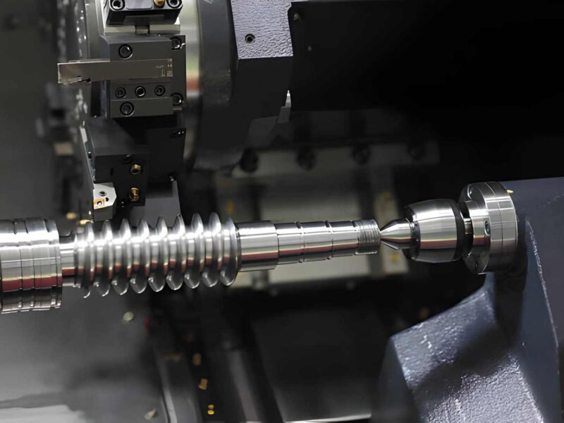
Straightness becomes particularly important when it comes to long turned parts. Often, cutting forces, heat, residual stress, or even how the part is simply clamped can cause a subtle bend that is not very visible during everyday work. However, if this bend is not controlled, the parts that apparently seem fine on their own will start causing problems the moment they become a part of some larger assembly.
Not sure if your current process can hold the tolerance your drawing calls for? Share your specifications with us, and we will help you make the decision.
Reading and Interpreting a Straightness Callout
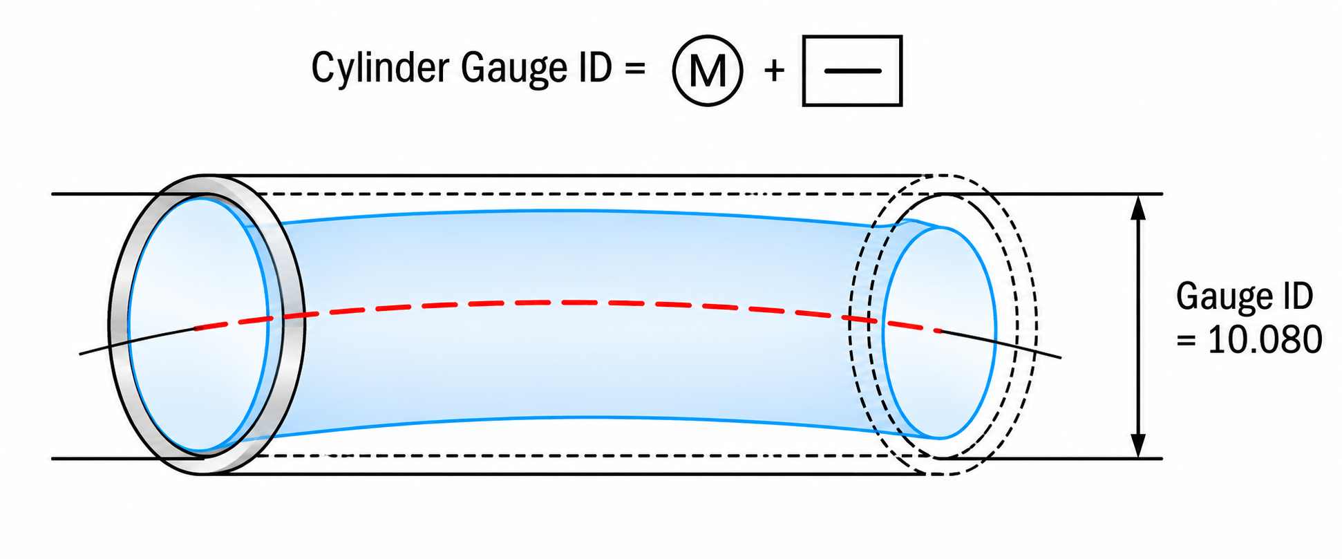 Straightness Callout
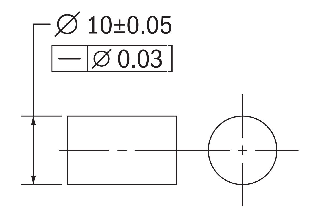
A straightness callout appears on a drawing as a feature control frame. This frame contains three things: the straightness symbol, which is a single horizontal line, followed by the tolerance value. There is no datum reference because straightness is a form control and does not relate the feature to anything else on the part.
Now, the location of the feature control frame on the drawing indicates what is being controlled. If it is attached to a surface with a leading line pointing to the surface itself, it is controlling the line elements on that particular surface.
If it is placed below the diameter dimension of a cylindrical feature, it is certainly controlling the axis/median line of that feature. This placement difference is important because the two applications have different tolerance zones and, therefore, have to be measured differently.
Summing it up, reading a straightness callout starts with identifying where it is placed, then looking at the tolerance value to understand how much deviation is actually allowed.
Components of a Straightness Callout
| Callout Element | Symbol / Example | What It Indicates |
|---|---|---|
| Straightness Symbol | ─ | Identifies the geometric control as straightness. The symbol is always the first element in the feature control frame. |
| Tolerance Value | 0.03 | Defines the maximum permitted straightness deviation. The feature must remain within this tolerance zone along its full length. |
| Feature Control Frame | | ─ | 0.03 | | Holds the geometric symbol and tolerance value. Since straightness is a form control, no datum reference appears in the frame. |
| Leader Line to a Surface | Frame attached to a surface | Controls the straightness of individual line elements on the specified surface. Each line is evaluated independently. |
| Callout Below a Diameter Dimension | Attached to ⌀20 | Controls the derived median axis of a cylindrical feature such as a shaft, pin, or dowel. |
| Diameter Symbol (if used) | ⌀ 0.03 | Indicates a cylindrical tolerance zone for axis straightness instead of two parallel lines used for surface straightness. |
| Datum Reference | None | Straightness does not require a datum because it evaluates only the form of the controlled feature. |
How Tolerance Zones Apply to Straightness Control
The tolerance zones are exactly what give a straightness callout its meaning. It defines the exact boundary that a line element or central axis must stay within from one end of the feature to the other.
The size and shape of that zone are not fixed; it can change based on what the callout is controlling, which is why understanding how the zone works is just as important as knowing how to read the symbol.
Straightness as One of the Form Controls in GD&T
Typically, all form controls in GD&T are a specific category of geometric controls that define a feature based on its own shape. Anything else, like its position, its orientation, or its relationship to any other feature on the part, does not matter. Straightness also belongs to this category.
When a straightness tolerance is applied, it is only important to ensure that the feature is straight enough on its own terms. Beyond this, no other factor affects the final evaluation. This makes straightness count among one of the most self-contained controls in the entire GD&T system.
How the Tolerance Zone Behaves Differently for Surfaces and Axes
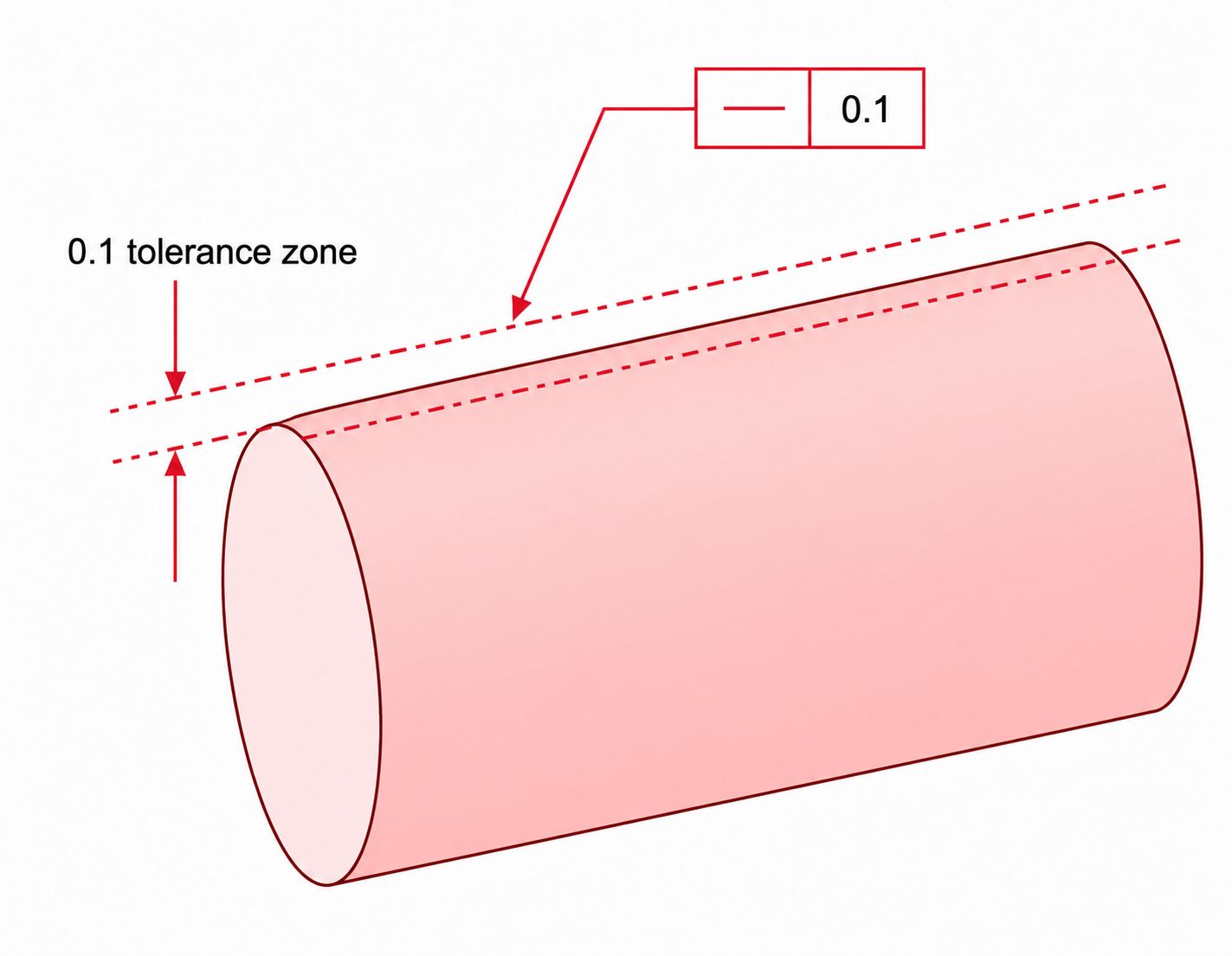 Straightness tolerance zone
For a surface, the tolerance zone is two-dimensional: there are two parallel lines separated by the specified tolerance value. Line elements running along the surface in the controlled direction are individually measured against that flat zone.
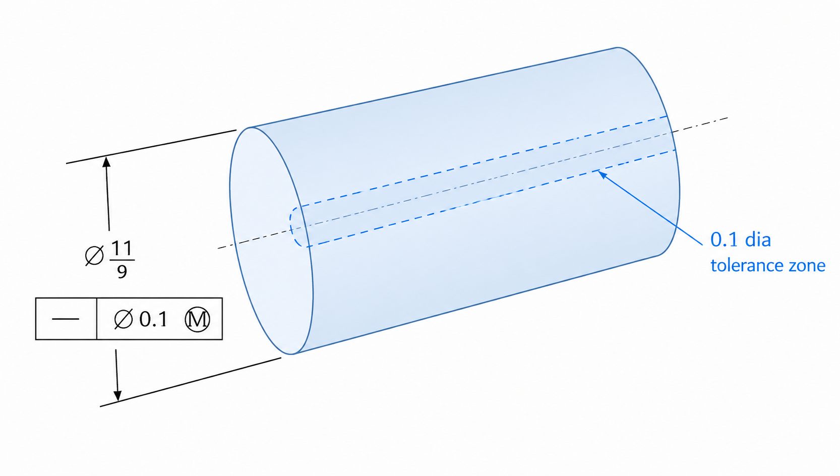
For a cylindrical feature, however, the zone becomes three-dimensional. It takes the form of a cylinder. The diameter of this cylinder is equal to the tolerance value. The median line of the feature, which connects the center points along itself, is required to stay inside the cylinder from end to end.
Since they are both fundamentally quite different zone geometries, mixing them up leads to misread drawings and consequently incorrect inspection of parts.
Want us to review your drawing for straightness callouts before machining begins? Send it over, and let our engineering team review it for you.
Why Straightness Needs No Datum to Function
Most GD&T controls require a datum. It is a reference point or surface from which the measurement is taken. Straightness, however, does not require one. This is because it only evaluates the shape of the feature itself, and nothing else. So the final result either tends to fall within the tolerance zone or outside it.
How to Define Straightness Tolerances on Engineering Drawings
The selection of straightness tolerance is a significant decision because the chosen tolerance value must reflect what happens to the part in reality when the respective feature is not straight. It may possibly affect assembly clearance, load distribution, sealing, or even fatigue performance, and this then determines how tight or loose the tolerance actually has to be.
How Tight or Loose Should the Tolerance Be
- Loose Tolerance: Generally, loose tolerances within the range of 0.1- 0.5 mm work well for three scenarios: first, non-critical features, second, long spans on which minor deviations would have no impact, and lastly, when the current output of the process already conforms to the range.
- Tight Tolerance: Contrary to the previous discussion, tight tolerances within the range of 0.01- 0.05 mm are required for features where even a small deviation can drastically affect the functioning of a part. For example, bearing seats, sliding fits, and sealing surfaces
Matching the Tolerance to Functional and Fit Requirements
The straightness tolerance is always required to stay below the functional limit it is protecting, and never equal to it. For example, if the limit is at 0.25mm, then the tolerance must be 0.20mm or less.
Manufacturing Limits
If the tolerance chosen is tighter than the capability a process can reliably offer, it will only build unnecessary inspection costs without having any positive effect on part quality. On capable equipment,
- CNC turning typically holds axis straightness in the 0.02- 0.05 mm range, on shafts up to 300mm, but varies by support and material.
- Cylindrical grinding holds 0.005 – 0.01 mm.
- Centerless grinding holds 0.005 – 0.015 mm.
- Surface grinding holds 0.005 – 0.01 mm per 300mm on surface line elements.
- Precision thread grinding and lapping can reach below 0.005mm.
Practical Ways to Control Straightness in Manufacturing
| Manufacturing Area | To-do |
| Cutting Parameters | During the finishing passes, reduce the feed rate and depths of cuts. |
| Tooling | Use sharp and properly grounded tools. |
| Grinding | Use either cylindrical or centerless grinding to achieve tight tolerances. |
| Thermal Control | Before finishing, let the parts and machine reach stable temperatures. |
| Drawing Callout | Always specify if surface or axis straightness is needed. |
Conclusion
Straightness is among the tolerances that have a significant impact on how a part performs in actual conditions. At Premium Parts, we work with straightness callouts across a wide range of applications, from general industrial components to high-precision shafts and bearing seats. Whether you already have a fully toleranced drawing or you’re still working out the details, our team is ready to help you get it right from the start.
Just reach out to us! Send us your drawings or tell us about your application, and we’ll get back to you with a quote and any engineering input your design might need.
FAQs
Can you machine my parts with tight straightness requirements?
Yes, depending on your tolerance requirements, we may work with CNC turning, cylindrical grinding, and centerless grinding to reach your tolerance requirements.
I’m not sure what tolerance to specify for my part. What should I do?
It depends on the purpose and function of the part. If you’re confused, reach out to us, and our engineering team will help you decide the right tolerance for you.
What if my part fails straightness during production?
If there would be any issues, we would catch them before the parts even ship. If the part has anything that needs to be reworked, we will reach out to you promptly and communicate it to you.
Does straightness tolerance affect the final price of my part?
Tighter tolerances generally require a more controlled process, strict conditions, and additional setups, all of which will ultimately add to the pricing. However, we’ll make sure you’re aware of everything when we make the quote to you.
Request a quote today, and we’ll break it down clearly for you.