Have you ever assembled furniture and wondered why some parts connect meticulously, while others require much force to connect? Engineers, in particular, as well as architects, do face such problems, although in a much more sophisticated and sensitive way. Fits in engineering confirm that all mechanical components must connect reliably and perform as intended. Understanding fits is important to achieve reliability, high efficiency, and precision in any manufacturing process.
Whether it’s sheet metal fabrication, injection molding, CNC machining, or other mechanical procedures, the selection of fits dictates the assembly, longevity, and performance of all components and the assembly as a whole. Learning basic fits is beneficial to engineers, machinists, and everyone else who wants to keep improving mechanical equipment. Let’s get into more details about Engineering Fits.
What is Engineering Fits?
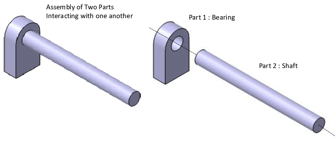
 Fits in Engineering
Image Description: The image shows a 3D model cutaway of a transition fit between a shaft and a gear bore, illustrating partial contact that allows limited movement before locking.
Engineering Fits serve as an intermediate between two mechanical components, such as a shaft and a hole. It simply states how well and closely a component fits during the assembly or operation of a particular piece of equipment. Normally, there are issues in the operation of assemblies with inappropriate fits.
The working of fits is not limited to connecting assemblies solely. Rather, it evaluates and confirms how well two components synchronize with each other. For instance, take the case of a car steering wheel; design engineers make sure that it is well-fitted to work without any external load. Besides, the steering must have an optimal balance in the assembly connection.
Suppose we have a piston in an engine cylinder. It must be able to slide and at the same time cannot be too slippery to cause overheating/friction. Aside from this, it cannot be too rough to cause leaks and other damage. Such precision, which defines why engineering fits, is the foundation of effective assemblies in mechanical systems.
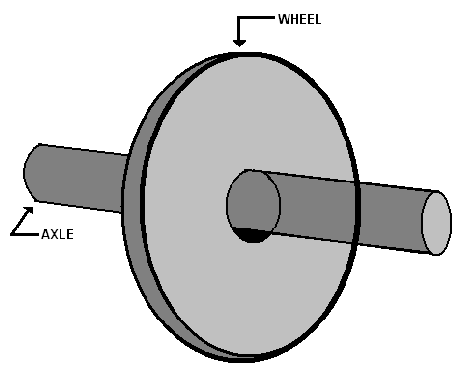
Holes and Shaft System In Engineering Fits
Fits are normally associated with hole-based or shaft-based systems. In the hole-based system, the internal component remains constant while the outer side of the component is adjusted according to application accuracy and tolerance requirements. This influences the flexibility of the structure, mobility of components, and precision measurement.
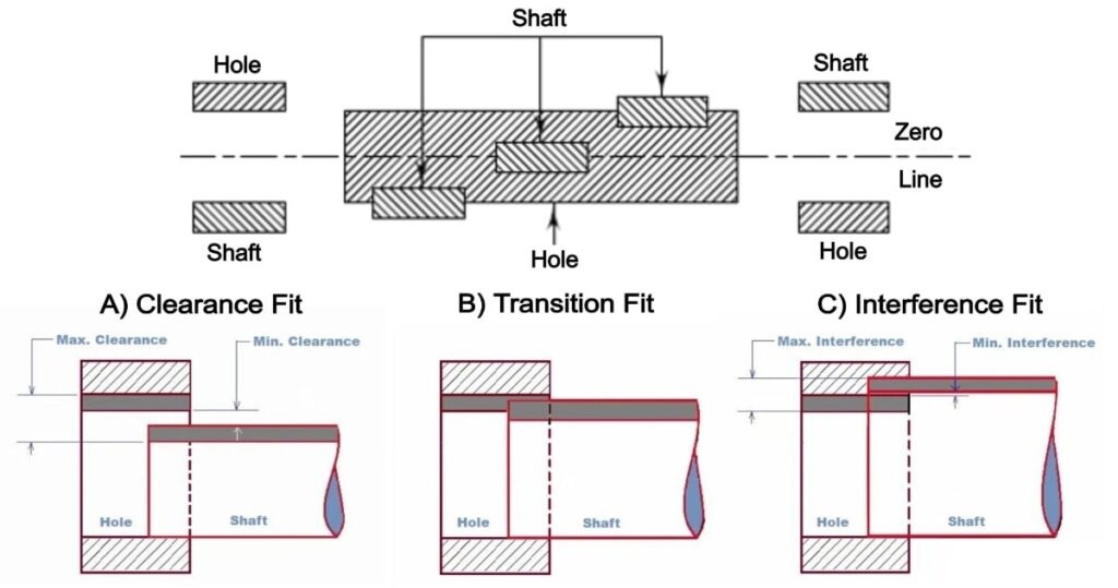
On the other hand, in a shaft-based system, the shaft’s dimensions are initially fixed, and the hole dimensions are adjusted to meet the tolerance requirements. Tolerance limits are covered by standards like ANSI and ISO, which also categorize fits. These will be explored in the later section. The following figure illustrates both systems according to three major types for better understanding.
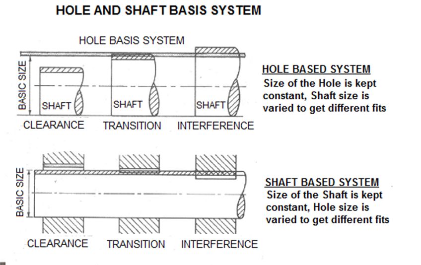 Hole and Shaft Basis System
Image Description: The image shows an engineering diagram comparing the hole-basis and shaft-basis systems, with labeled tolerance zones on a dimensional scale.
What makes Engineering Fit Crucial in Manufacturing?
Let’s talk about why engineering fits are a prime factor in manufacturing:
- Fits Promote Durable: When loads are applied to any assembly, appropriate fit installation eliminates the chances of body wearing, deforming, and even assembly failure.
- Optimum Functionality: Correct fits allow components to interact and function as desired in stationary and moving applications.
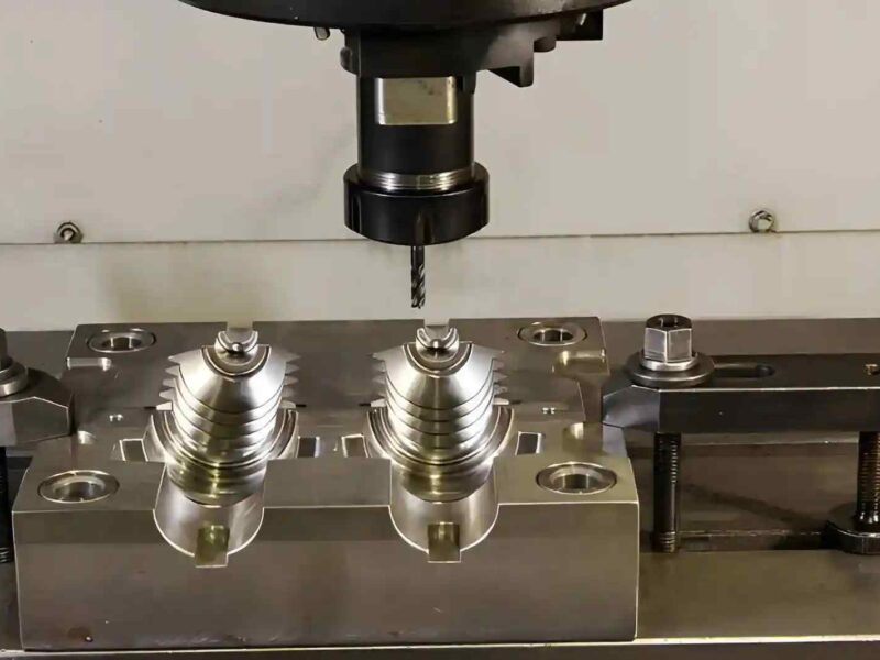
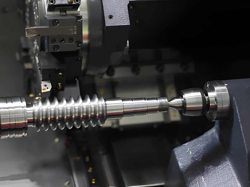
- Precision: In high-tech manufacturing, such as CNC machining, narrow tolerance limits of any machinery are achieved through the installation of an accurate fit.
- Safety: Bad fits could result in, for example, an overly tight axle and maybe a loose steering wheel — some serious safety implications.
Three Essential Types of Fits
Engineering Fit Types vary based on the shaft and hole dimensional constraints. Let’s discuss them in detail:
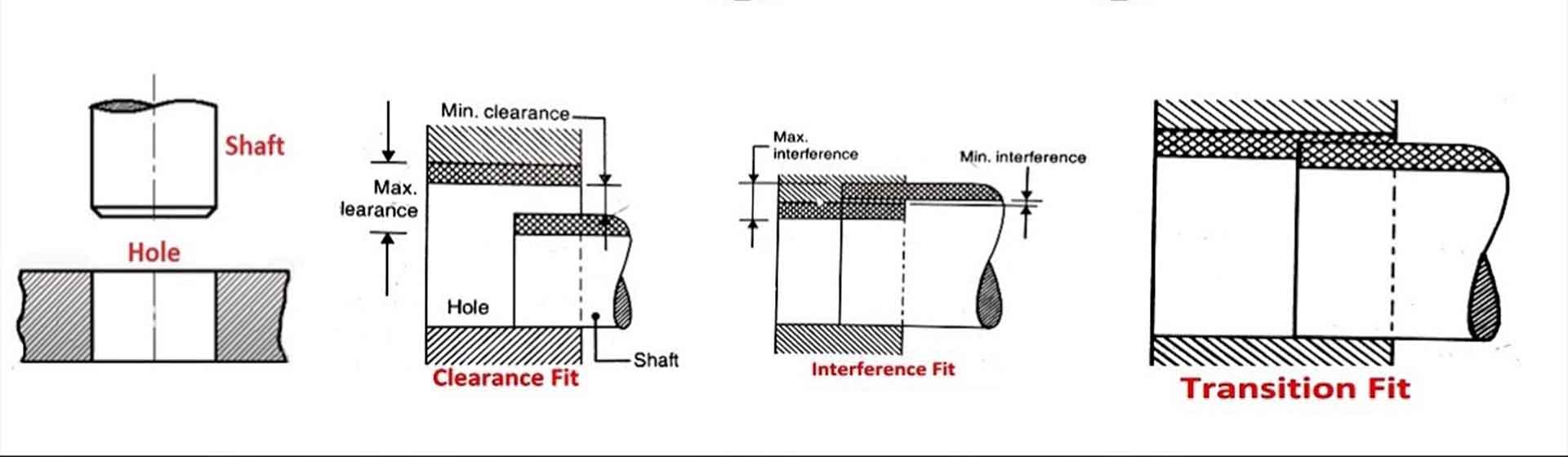
Type 1: Clearance Fits: Freedom of Movement
 Clearance Fit
Image Description: The image shows a labeled tolerance chart with upper and lower limits of the shaft smaller than the hole.
Clearance fits allow the components to be in contact, and you can slide over the other without any friction. Besides, it involves a space between the shaft and the hole so that it may turn freely under all conditions. For example, the axle of a skateboard wheel requires it to spin smoothly to perform.
“Engineers use clearance fits with a positive(+) allowance for dimensional accuracy. This fit’s shaft diameter remains less than the largest hole’s diameter.” In this, tolerances like ISO H7/g6 or H8/f7 confirm strict controls. Such fits are used in wheel bearings, hinges, and sliding doors. It enables considerable flexibility, thereby maximizing its utility and effectiveness for dynamic uses.
Subtypes of Clearance Fits:
- Loose Running Fit (H11/c11): Loose running fit is ideal for use where there is sufficient space, such as low-speed shafting.
- Sliding Fit (H7/g6): Sliding fit types provide limited but not excessive freedom of movement, as in machine tool spindles.
- Close Running Fit (H7/f7): Used in applications where moving parts require high accuracy in moderate-speed operations.
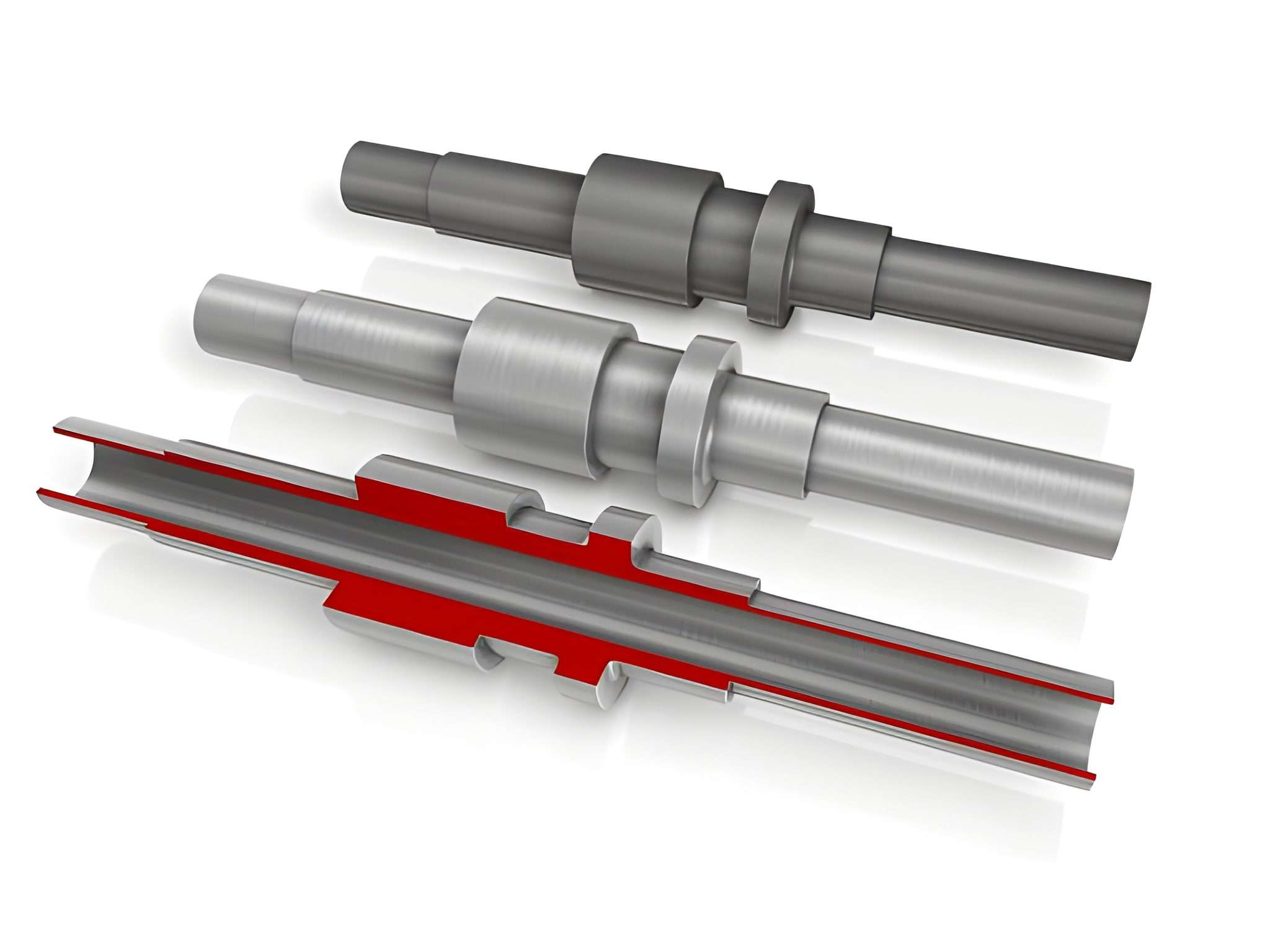
Type 2: Transition Fits: Balanced Connections
 Transition Fits
Image Description: The image displays a 3D model of a transition fit assembly. It highlights near-perfect alignment between the shaft and hole surfaces to indicate close contact.
Transition fits are always somewhere in between clearance and interference fits. These fits allow parts to join with little force, confirming easy disengagement. Besides, it provides adaptability, easy disassembly, and support under normal working conditions.
Typically, the transition fits follow ISO standard types like ISO H7/k6 or H7/m6. For example, a dowel pin used in the machinery confirms that components are in a position through precise positioning of the dowels, yet there is no need for a permanent fix.
Some of their uses include gear, cleaner suction accessories, anchor bolts, and USB connectors. Transition fits are perfect for activities needing semi-permanent connections and pliability in motion.
Subtypes of Transition Fits:
- Light Push Fit (H7/m6): These fits demand minimal force for engagement and disengagement.
- Medium Push Fit (H7/k6): Provision of stability during normal loads while permitting separation for some specific loads.
- Tight Transition Fit (H7/n6): These provide rigidity, which is essential where alignment of the mating parts is necessary for joining.
Type 3: Interference Fits: Permanent Stability
Interference Fits
Image Description: The image displays a 3D cutaway rendering of an interference fit, with the shaft and hole shown in full contact.
Interference fits provide a close, tight clasp of the two components. “In this kind of fit, the size of the shaft is always greater than the size of the hole, and hence forms a press fit”. Every time, using interference fits demands the application of force, heat, and special techniques of fitting.
ISO codes, such as ISO H7/p6 or H7/u6, control the accurate operation and tightness of interference fits.
Subtypes of Interference Fits:
- Force Fit (H7/p6): They need a high power to be attached, which is why they are ideal for use in mechanical settings.
- Shrink Fit: The outer part of the product in group B needs to be heated to expand and then fit the other parts of the product.
- Heavy Interference Fit (H7/u6): They provide optimum utilization for the connection of high-load and permanent ones.
What Is The Significance of Engineering Fit Standards
 Clearance, Interference & transition fits
Image Description: The image shows a tolerance diagram with ISO notations, H7/g6 for clearance, H7/k6 for transition, and H7/p6 for interference, indicating standard engineering applications.
The standards established by ISO and ANSI are rigid regarding fits. Fits need to be compared and followed according to standard instructions to get the optimal results. These standards state the parameters of shafts and holes, including their corresponding tolerance values. Moreover, they also divide different types of fits into classes, thus making it easier for machinists and engineers to choose from.
Experts align parts properly to verify that no problem arises when assembling it, or even if it fails. So, it confirms that assemblies remain durable, reliable, and highly functional. Besides, it enables machinists to confidently select the right fit for their applications.
Whether it is a small precision measuring tool or a big power tool, these fit standards are closely relevant. They help reconcile material requirements with durability, performance, and ensure high manufacturability.
How To Select the Right Engineering Fit?
Various crucial factors are considered while selecting the optimal fit. Let’s discuss them:
Purpose of Your Connection:
- How long do parts need to stay together?
- Will the components need movement, and if so, then to what degree of freedom?
- What kind of intensity of loads will the components need to carry?
Operating Conditions:
- The use environment, that is, exposure to corrosive substances and humidity.
- The temperature at which the equipment operates and its prospect of undergoing thermal expansion/contraction.
- Visitation frequency and the rate at which it moves from one part to another.
Assembly Requirements:
- Access to disassembly or maintenance
- Production volume and linked time constraints
- Equipment and tools for assembly
Common ISO Standard For Standard Engineering Fits
ISO standards are accepted and highly practiced standards for choosing accurate connections. ISO-286-2 defines the standard tolerances for shafts and holes. The following tables show the common ISO number and applications of each fit subtype.
| Type of Fit | Fit SubType | Applications | Hole Basis | Shaft Basis |
| Clearance Fit | Loose Running Fit | Pivots, parts with corrosion and dust, parts exposed to thermal changes | H11/c11 | C11/h11 |
| Free Running Fit | Cylinder-piston assemblies, slow-rotating parts | H9/d9 | D9/h9 | |
| Close Running Fit | Machine tool spindles, shaft bearings, and sliding joints | H8/f7 | F8/h7 | |
| Sliding Fit | Sliding gears, clutch disks, hydraulic pistons | H7/g6 | G7/h6 | |
| Locational Clearance Fit | Machine tool guides, roller guide rails | H7/h6 | H7/h6 | |
| Transition Fit | Locational Transition Fit | Wheels, brake disks, gears/pulleys on shafts | H7/k6 | K7/h6 |
| Locational
Transition Fit |
Motor armature windings, gears | H7/n6 | N7/h6 | |
| Interference Fit | Locational Interference Fit | Hubs, clutches, bushings for bearings | H7/p6 | P7/h6 |
| Medium Drive Fit | Permanent gear/pulley assemblies, bearing mounting | H7/s6 | S7/h6 | |
| Force Fit | Flange mounting, gears, and shafts | H7/u6 | U7/h6 |
What Are The Common Mistakes To Avoid When Designing Fits?
Let’s discuss a few prevalent practices in the industry that compromise the functionality of fits. Firstly, it refers to the inappropriate tolerance selection of fits. Because it results in either loosening or sometimes tightening of the connection. So, it can cause assembly separation issues. Similarly, optimal temperature range consideration is of similar importance. Especially for materials having high thermal coefficients. If it’s not considered, it could result in excessive contraction and expansion due to temperature change.
Last but not least, select fits as per their maintenance and disassembly allowance. If you choose the wrong fit, it can limit your maintenance options after a predefined time interval. Since these mistakes can have a serious impact on the overall operation.
Best Practices To Opt For Avoiding These Issues:
- Regardless of the application, international standards like ISO for fits must be studied and practiced right from the design phase.
- Utilize international standards and manufacturer guides to finalize the appropriate material.
- Anticipated operating parameters must be effective for the functioning of the plan at the initial stage.
Applications of Fits in Engineering
Fits are useful in various industries for confirming accurate assembly and desired component functionality. Here are a few common applications:
- Automotive: Engineers use bushings (fit type) in automotive engines, steering systems, transmissions, and other assemblies where linear/rotational movement is needed.
- Aerospace: Designers confirm the accuracy, reliability, as well as safety of aircraft parts by choosing precise fits.
- Medical devices: Engineering fits affirm the prolonged usage of different implants and surgical instruments.
- Customer Electronics: These give a continuous user experience and reliability in products such as USB ports.
At Premium Parts, we provide our customers with near-close tolerance engineering fits. Our engineers incorporate advanced CNC machining and manufacturing technologies. So, reach out to us and get an instant quote from our qualified staff!
What Are The Future Trends in Engineering Fits?
The future of engineering is promising. Because of the latest developments in technology, more advancements are expected. Further, continuous manufacturing process evolution is also occurring at an exponential level. The following are some techniques/materials that help these transitions:
- Smart Materials: Engineers can choose diverse materials that can adapt to environmental changes and avoid assembly failures. Additionally, these increase the fit’s usefulness and functionality.
- Advanced CNC Machining: Manufacturers can tolerate more, and new advanced machines allow them to be more accurate in custom design fits.
If you’d like to know how to choose/select and achieve the right fit for your application, contact Premium Parts. Our professional engineers give you recommendations to optimally resolve your concerns.
FAQs
Q1. What role do engineering fits play in reliable assemblies?
Engineering fits are used to control the part interactions in assemblies. Also, these fits improve the performance and product strength for longer use.
Q2. What is the role of tolerance in fit quality?
Tolerances allow parts to sway gaps and adjust dimensions. In addition, the selected tolerances ease assembling and performance without compromising on high quality.
Q3. Which industries use engineering fits?
In general, automotive, aerospace, medical device manufacturers, and electronics sectors need accurate fitting to validate the safety, accuracy, and performance of components.
Q4. How does Premium Parts guarantee fit to be precise?
At Premium Parts, we offer precise mechanical fits by employing various manufacturing techniques—such as CNC machining, strict quality control procedures, and international standards in place to provide accurate and precise fits for your engineering project.