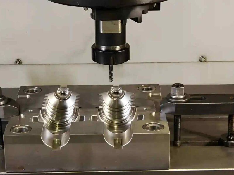
Surface grinding in CNC is usually performed after milling. For example, it is done when the part still does not sit flat during inspection. You may machine a plate, measure it, and still see light gaps on a surface plate or uneven contact with a mating part. At that stage, grinding is used to remove a very thin layer and bring the surface into full contact across the part.
In machining, surface grinding removes only a small layer of material. Even small changes in wheel sharpness or heat at the contact point can shift the final flatness or leave light surface marks. Because of this, it is treated as a final finishing step, unlike rough machining operations.
This article will cover:
- How the surface grinding process works in CNC
- When to use grinding after milling or heat treatment
- Types of surface grinder machines used in shops
- Step-by-step process from setup to inspection
- What controls surface finish and flatness
- Common issues and how they are handled in production
What Is Surface Grinding in CNC Machining
Surface grinding in CNC machining is used when a milled face does not sit properly during inspection. You can machine a plate, clean it, and still notice slight rocking or uneven contact on a surface plate. Grinding is used at that point to take off a very thin layer and correct the contact face.
It works with an abrasive wheel instead of a cutting tool. The wheel touches the surface with small abrasive points, removing material in very small amounts. Because of this light contact, it is used at the end of machining on plates, blocks, and heat-treated parts where milling marks or small height differences remain.
In most workshops, this process is used on base plates, die blocks, and fixture parts after milling or heat treatment. The main purpose is to correct the face so it sits properly during assembly or checking.
How Surface Grinding Works
Surface grinding follows a clear sequence. Each step prepares the part for the next, so the final surface sits flat and matches the drawing.
Machine setup and part alignment
The part is placed on a magnetic chuck or fixture. The operator checks if it sits evenly before grinding starts. A quick indicator check helps confirm there is no tilt across the surface. If the part is not seated properly, grinding will remove material unevenly.
Rough grinding passes
The first passes remove the outer layer left from milling or heat treatment. The wheel moves across the surface with a light depth of cut, usually in small steps. At this stage, the goal is to clean the surface and bring it closer to the final size without overheating the part.
Semi-finish passes
After rough passes, the grinding depth is reduced. These passes help remove marks left by earlier cuts and improve surface contact. The operator may dress the wheel again before this stage to keep the cutting edge sharp.
Finishing and spark-out
Final passes are very light. The machine may run a few passes without further infeed, known as spark-out. This helps remove small high spots left from previous cuts. At this stage, surface marks become finer, and the part sits better on a flat reference.
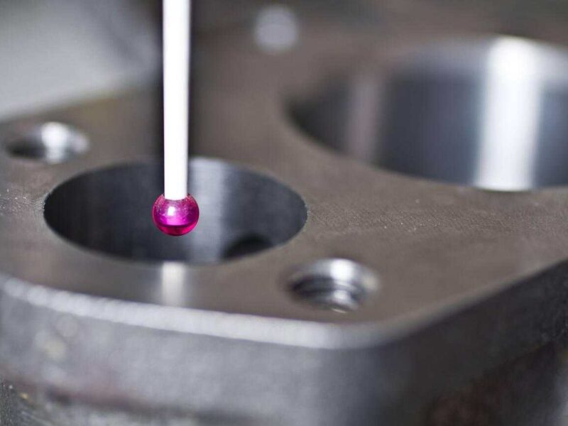
Inspection and checking
After grinding, the part is checked on a surface plate. Flatness is verified using a dial gauge or straight edge. Thickness is measured to confirm it matches the drawing. If needed, a few light passes are repeated to correct small variations.
What is the Finishing and Spark-Out Process in Grinding
Finishing in Surface Grinding
- Finishing in grinding is the final stage, with very light material removal after earlier passes
- Used when the part is already close to its final size and only surface correction remains
- Removes remaining marks and prepares the face for proper contact during inspection
Spark-Out Process
Spark-out comes right after the last infeed. The machine keeps running passes without moving the wheel deeper into the part. Even without infeed, the wheel still removes slightly high spots caused by machine deflection and contact pressure during earlier passes. This helps the surface settle and improves how the part sits on a flat reference.
Finishing vs Spark-Out in Surface Grinding
| Parameter | Finishing Pass | Spark-Out Stage |
| Infeed (depth of cut) | Very light (≈ 0.002–0.01 mm) | No infeed |
| Purpose | Clean the surface and reach the final size | Remove remaining high spots |
| Wheel condition | Freshly dressed wheel preferred | Same wheel, no dressing |
| Table movement | Normal feed rate | Slower feed or repeated passes |
| Material removal | Controlled, minimal | Very small, from surface peaks |
| Surface result | Finer grinding marks | Smoother contact across the surface |
| Role in process | Final sizing step | Stabilizes the surface after finishing |
Types of Surface Grinders
Different surface grinders are used based on part shape, size, and how the surface needs to be finished. They usually differ in spindle direction and table movement
Horizontal spindle surface grinder
As the name suggests, in horizontal spindle grinding, the wheel is mounted horizontally, and the outer edge of the wheel contacts the part. It is used for flat plates, blocks, and general machining work.
The table moves back and forth, while the wheel feeds down slowly. This setup gives better control on flat surfaces and is widely used for tool room and production grinding.
Vertical spindle surface grinder
In this type, the wheel is mounted vertically, and the face of the wheel grinds the surface. It covers a larger contact area in one pass, which helps when removing material from larger surfaces.
It is often used for bigger parts where faster surface coverage is needed, but it may leave a different surface pattern compared to horizontal grinding.
Reciprocating table surface grinder
This machine uses a table that moves in a straight back-and-forth motion under the wheel. It is used for rectangular parts and long surfaces.
It allows step-by-step material removal across the surface and gives better control when working on precision flat faces.
Rotary table surface grinder
In this setup, the table rotates instead of moving back and forth. The part spins under the grinding wheel, which allows continuous grinding.
It is used for round parts, rings, and components where uniform surface contact is needed across a circular area.
CNC surface grinder
CNC surface grinders use programmed control for table movement, wheel feed, and grinding passes. This reduces manual adjustment during the process.
CNC surface grinders are used to mold base plates, die plates, fixture plates, hydraulic valve blocks, and bearing housings.
Differences Between Surface Grinder Types
| Type | Spindle Direction | Table Motion | Contact Area | Best Use Case |
| Horizontal spindle | Horizontal | Reciprocating | Line contact (wheel edge) | Flat plates, precision surfaces |
| Vertical spindle | Vertical | Reciprocating or rotary | Large area (wheel face) | Large flat surfaces |
| Reciprocating table | Horizontal or vertical | Back and forth | Controlled step grinding | Rectangular and long parts |
| Rotary table | Horizontal or vertical | Circular rotation | Continuous contact | Round parts, rings |
| CNC surface grinder | Horizontal or vertical | Programmed motion | Depends on setup | Batch production, repeat jobs |
When Should You Use Surface Grinding
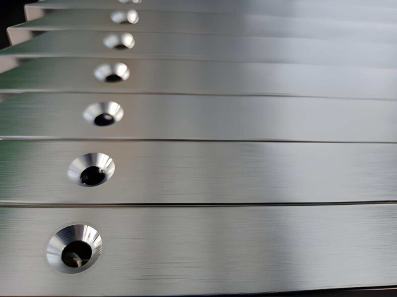
- When large flat faces show height variation after milling
- When thin or long parts shift shape under clamping pressure
- When tool deflection creates a taper across long machining surfaces
- When mating faces need full contact for sealing or fit
- When surface marks from milling affect the sliding or contact function
- When hardened material reduces the cutting tool performance after heat treatment
- When a final correction is needed after machining or heat-related distortion
Typical Surface Roughness Range (Ra) in Surface Grinding
Surface grinding is used to achieve fine surface quality after milling and heat treatment.
- The actual Ra value depends on wheel condition, feed rate, and finishing passes, but it generally falls in a narrow controlled range compared to cutting processes.
Typical Surface Roughness (Ra) Range
| Process Stage | Typical Ra (µm) | Practical Result |
| Rough grinding | 1.6 – 3.2 µm | Removes milling marks, prepares surface |
| Semi-finishing | 0.8 – 1.6 µm | Reduces visible tool marks |
| Finish grinding | 0.4 – 0.8 µm | Smooth contact surface for assembly |
| Precision grinding | 0.2 – 0.4 µm | Fine fit surfaces, sealing faces |
What is the Difference Between Surface Grinding, Milling (Finishing), Honing, and Lapping
These four processes are used for finishing, but they solve different problems. The right choice depends on surface type, required finish, and how accurate the contact needs to be in assembly.
CNC Surface Grinding
Surface grinding uses a rotating abrasive wheel that removes a very thin layer from flat surfaces. It is used after milling or heat treatment when the surface is not fully flat or shows distortion. It is suitable for plates, blocks, and hardened parts where flat contact is needed in assembly.
Milling (Finishing)
Finishing milling uses a cutting tool to generate the final surface during machining. It is fast and flexible, but the tool leaves visible feed marks on the surface. It is used when flatness and finish requirements are moderate, and parts do not need precision contact.
CNC Honing
Honing uses abrasive stones that expand inside a bore and rotate with slow movement. It corrects the shape inside holes rather than flat faces. It is used for engine cylinders, hydraulic bores, and any internal surface where smooth sliding contact is needed.
Lapping
Lapping uses a flat plate and fine abrasive slurry between the part and the surface. The process is very slow and removes only microscopic material. It is used when sealing surfaces or precision gauges need near-perfect contact.
Comparison Table for Selection
| Process | How it works | Best surface type | When to choose |
| Surface Grinding | Abrasive wheel removes a thin layer from the flat face | Flat external surfaces | When milling leaves with uneven height or distortion |
| Milling (Finishing) | Cutting tool forms surface during machining | General flat or shaped surfaces | When the finish requirement is normal and speed matters |
| Honing | Expanding abrasive stones inside the bore | Internal cylindrical surfaces | When a bore needs smooth sliding contact |
| Lapping | Part rubbed on the plate with an abrasive slurry | Very fine flat or sealing faces | When sealing or gauge-level contact is required |
Applications of Precision Surface Grinding
Surface grinding is mainly applied where two machined surfaces must meet evenly during assembly, and where load is transferred through flat contact areas.
Mold, Die, and Tooling Components
Surface grinding is used on mold and die plates to remove small height differences left after milling. It helps prepare mating faces so that tooling closes without gaps during operation. Fixture plates also use grinding to improve contact with locating and clamping surfaces.
Machine Base and Structural Interfaces
Machine bases and fixture structures use surface grinding on mounting faces to improve contact with assembled parts. Uneven areas from rough machining are corrected so components sit properly during tightening.
Hardened and Wear-Resistant Parts
After heat treatment, parts like wear plates and guide components become difficult to machine with cutting tools. Surface grinding is used to correct shape and prepare contact areas for assembly or movement.
What Are the Typical Surface Grinding Problems & Smart Tips on Fixing Them
Surface grinding issues usually show up on the finished face or during flatness checking. Most problems come from heat, wheel condition, holding setup, and vibration during contact.
Grinding burn and heat marks
Grinding burn happens when heat builds up at the contact zone. The surface may show brown or dark marks, and in some cases, the metal structure changes slightly near the top layer. It is usually caused by heavy infeed, dull wheel condition, or weak coolant coverage.
Fix
- Reduce the depth of cut per pass
- Dress wheel to restore cutting edges
- Direct coolant flow onto grinding contact area
Wheel loading and surface drag
Wheel loading happens when aluminum builds up on the wheel surface. Cutting action drops, and the surface starts looking smeared or uneven. This is common with softer aluminum grades and long continuous grinding runs.
Fix:
- Dress wheel during production cycles
- Select open structure abrasive wheel for aluminum
- Increase coolant flow in the grinding zone
Chatter marks and surface waviness
Chatter appears as repeated lines or wave patterns across the surface. It comes from the vibration between the wheel, the table movement, and the workpiece holding. It affects surface appearance and flatness reading.
Fix:
- Check the magnetic chuck holding strength
- Lower table feed speed
- Balance the grinding wheel condition
Uneven flatness after grinding
Some areas remain slightly higher after finishing passes. This usually comes from part movement during grinding, uneven seating on the chuck, or machine deflection under load.
Fix:
- Re-seat the part on the magnetic chuck
- Reduce material removal per pass
- Add a final spark-out cycle before inspection
When Surface Grinding Becomes Expensive
Surface grinding cost goes up when you need more time on the machine, more corrections, or more control checks during the process. It is not only the grinding time, but it is also the extra steps needed to bring the part back into the drawing limits.
Tight tolerance on flat faces
When you set very tight flatness or thickness on your drawing, you force very small cutting passes. You end up checking the part more often, and each small correction adds machine time. You also dress the wheel more frequently to hold the finish.
Large contact area parts
When your part has a large surface, every pass takes longer to cover the full area. You also need to slow the feed to avoid heat marks, which increases cycle time. The larger the face, the more time you spend per pass.
Distortion during grinding
If your part moves slightly after clamping or heating, you may need to re-grind the same surface. This adds extra setup steps and extra inspection before you can accept the part.
Hardened material condition
When you send heat-treated parts for grinding, the wheel wears faster and removes material more slowly. You end up stopping more often to dress the wheel, which adds interruptions during the job.
Contact Premium Parts For Custom Manufacturing Support
At Premium Parts Manufacturing, we support you with practical engineering input before production starts. Our team provides a free DFM review so you can check flatness, tolerance, and surface finish requirements before machining begins. We also follow ISO 9001:2015-based quality practices to keep production inspection clear and controlled.
- Free DFM review before production starts
- ISO 9001:2015 aligned quality inspection process
- Support for hardened steel, plates, dies, and fixture parts
- Batch production support with controlled surface finish
- Practical feedback on grinding feasibility and setup needs
Contact us today and send us your drawing to our team for a non-obligatory review before machining.
FAQs
What is surface grinding used for?
Surface grinding is used to correct flat faces after milling or heat treatment. It helps bring parts into proper contact for assembly, especially on plates, dies, and fixture surfaces.
What surface finish can grinding achieve?
Typical grinding finishes range from rough correction levels to fine finishing around 0.2–1.6 µm Ra, depending on setup and wheel condition.
Can surface grinding handle hardened steel?
Yes, it is commonly used on hardened steel parts above 50 HRC where cutting tools lose effectiveness.
Why is grinding used after milling?
Milling leaves tool marks and small height variation. Grinding removes a thin layer to correct these issues and improve surface contact.