Surface roughness has a substantial impact on object-environment interactions. The factor points to mechanical performance because roughness triggers crack and corrosion initiation. In certain cases, the solid surfaces with roughness have more wear and higher friction than smooth ones. Some applications require surface roughness because it improves the ‘bite’ that a coating, such as paint or plating, needs. Experts usually indicate the parameter Ra as surface roughness. This metric refers to the average surface heights along a profile calculated by simple addition. The measurement involves computing the average of the heights of microscopic peaks and valleys. The profilometer serves as a basic instrument for measuring the roughness, providing average surface irregularities from a reference line.
This article presents information on typical surface roughness finishes for CNC machining, which usually range from 3.2 to 0.4 micrometers Ra. Usually, CNC machining delivers precise tolerances of 0.025 millimeters. As a subtractive manufacturing process, CNC machining creates edges that introduce roughness to finished products.
Understanding of Surface Finish and Roughness
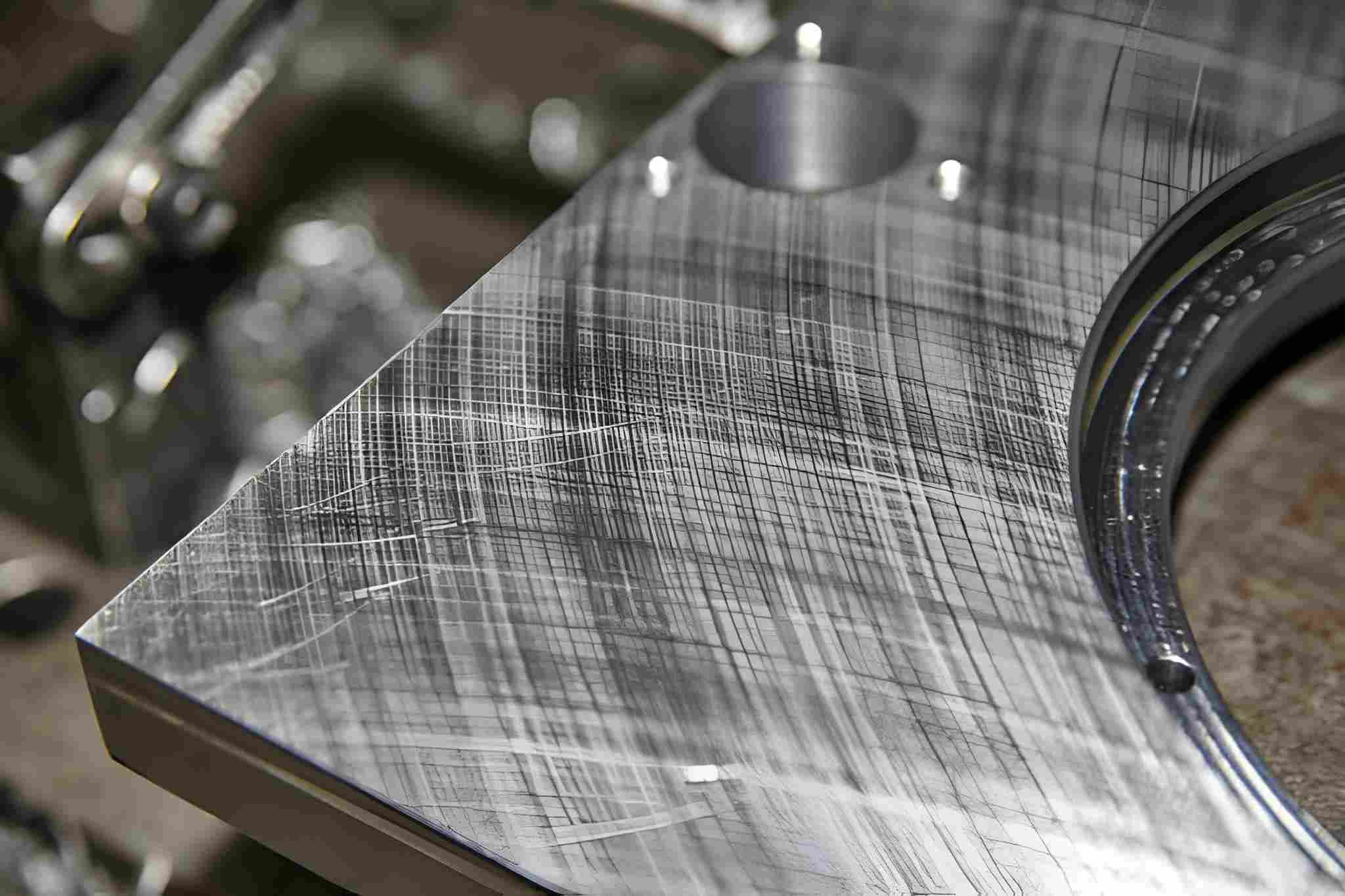
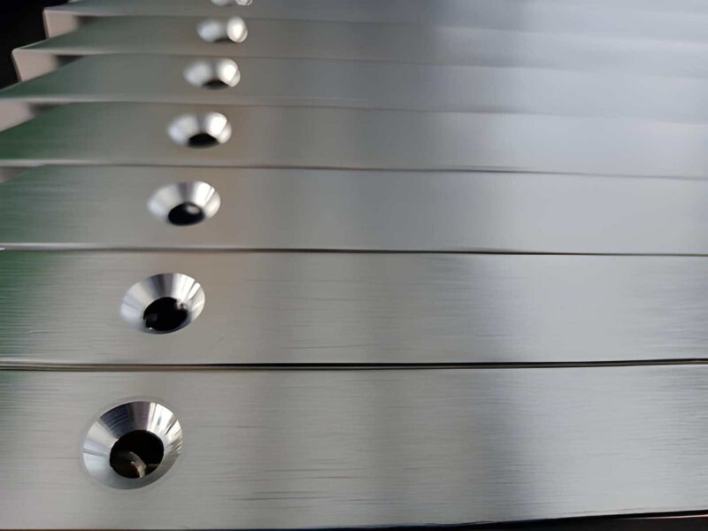
Stainless Steel Part Rougness
Image Description: An image showing a close-up view of a stainless steel part highlighting its surface roughness, with visible machining marks and texture.
Surfacing defines an outer characteristic that shapes a component’s surface. This activity includes techniques that modify the top surface of the material by adding, subtracting, or changing the metal. Three key aspects define surface finish: roughness, waviness, and lay.
- Surface Roughness: Surface roughness quantifies the total amount of irregularities on a metal surface; it counts the number of highs and lows. A lower roughness number shows less irregularity, resulting in a better surface finish. When specialists discuss surface finish, they pay particular attention to roughness.
- Waviness: Waviness is larger than other deviations due to causes such as deflection or vibration. It negatively impacts the measurement of the space between surface irregularities.
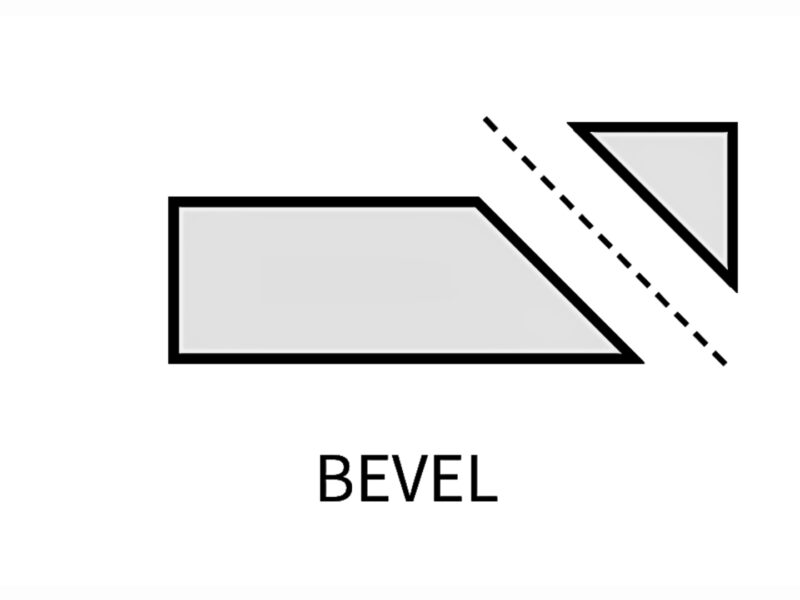
- Lay: Lay indicates the orientation of the principal surface textures.
Benefits of Machining Surface Roughness
Machined surface roughness offers numerous advantages that help to improve the performance and product life of manufactured items.
- Improved Surface Quality: Firstly, a key advantage of the process is surface roughening. These finishes create a smoother, more uniform surface with a higher quality compared to conventional methods.
- Adhesion Enhancement: Machined finishes promote coating adhesion and create a uniform surface for application. When the surface is smooth, coatings and paints create a protective layer on surfaces that provides better protection and lasts longer.
- Aesthetic Look: A smooth surface finish is aesthetically desirable, especially for consumable products. A pleasant appearance can help change the way customers think and act.
- Chemical and Electrochemical Corrosion: The use of machined finishes also protects parts from corrosion and chemicals. Particularly, it’s important for products being used in harsh conditions to be able to last longer.
- Increased Conductivity: These finishes increase electrical conduction and performance in various electronic devices.
- Strength Improvements: Last but not least, the machined surface finishes increase the part’s or product’s strength. They decrease the rate of wear and tear; hence, parts become stronger and more effective in their intended application.
Techniques For Measuring Surface Roughness
Surface roughness measures the surface profile texture of a component and hence plays an important role when evaluating surface roughness. The major measure employed in this evaluation is the Ra value, which measures the mean profile roughness. Understanding surface characteristics involves recognizing three key components: roughness, waviness, and lay. All of these elements are critical in the determination of the geometry of the surface in question. Common Measurement Techniques include;
Contact Measurement Method
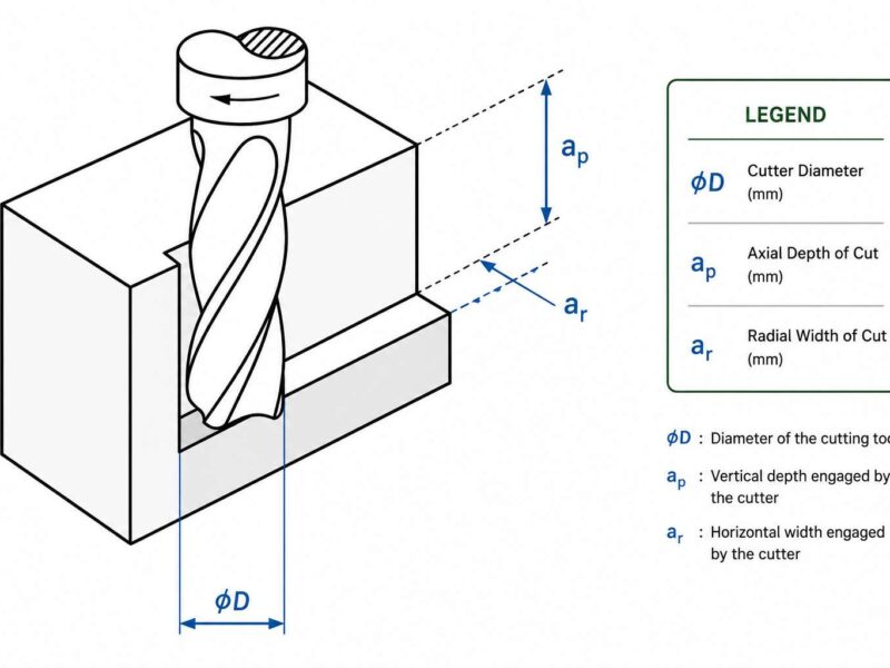
Contact measurement methods use stylus probes to assess surface roughness. In operation, the stylus is only slid up and down on the surface, and its movement is recorded. The resulting profile enables the determination of necessary surface roughness characteristics. Nevertheless, the technique may pose certain limitations. If contact is made on fragile surfaces, then it’s advisable to choose a stylus with a small diameter and apply a slight force during contact. This approach enables the preservation of the surface integrity and provides accurate values.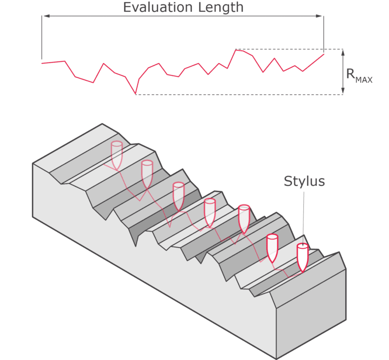
Contact Measurement Method
Image Description: An illustration showing the contact measurement method, with a labeled diagram highlighting how a measuring instrument, such as a micrometer or dial gauge, physically touches the workpiece surface to determine its dimensions accurately.
Contactless Measurement Procedures
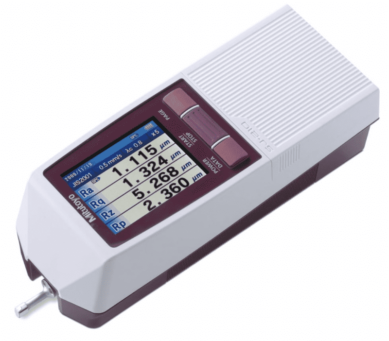
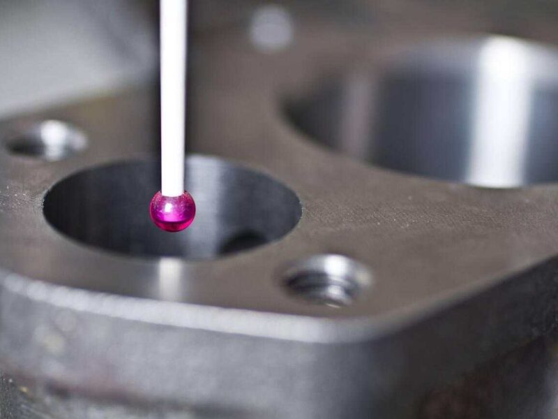
Digital Contactless Measurement with Displayed Values
Image Description: An image showing a digital measuring device performing a contactless measurement, with values displayed on the screen
Contact measurements are gradually being replaced with non-contact ones because the latter are faster. These techniques employ light-based tools, including lasers and X-ray systems, to measure surface roughness and are non-contact. The first method is optical scattering, in which ultrasonic impulses are directed to the material surface. These impulses are reflected to obtain surface roughness parameters by analysis of data. Moreover, microscopy techniques enable the study of micro-peaks, and the results are always uniform and accurate for any surface.
Comparative Measurement Approaches
Comparative/measurement methods include a process whereby a product’s surface is compared to a standard roughness. This benchmark surface can also be used as a standard, by which manufacturers can compare the appearance of their product’s surface both by sight and by touch. Such comparisons significantly help maintain the standardization of surface texture across different production batches.
In-Process Surface Roughness Assessment
Machining process control monitoring techniques allow the assessment of surface finish parameters at intervals throughout the machining process. This real-time assessment adds value to the manufacturing process. Because it doesn’t disrupt the production process and enables manufacturers to guarantee the quality, simultaneously.
Inductance Measurement Method
The inductance method works best for measuring the roughness of magnetic surfaces. It uses an inductance pickup that works by capturing the use of electromagnetic energy to determine the distance of the pickup from the surface. The data collected provides useful information on the comparative surface roughness.
Machine-Based Measurement Systems
Machine-based measurement systems use digital means to shed light on the product surface. After that, the data is conveyed to a computer for analysis after it has been illuminated. From the results of the analysis of the obtained data, using the reference charts of surface roughness, manufacturers can accurately define the parameters of the surface roughness.
Ultrasound Measurement Method
The ultrasound method is applied by the spherical sensors that send impulses in different directions to the surface. This technique helps identify the received impulses to measure the surface roughness parameters with high precision. This method has found its usefulness in that it does not invade the surface of the material and provides high-quality surface finishes.
Understanding Surface Roughness: Concepts, Terms, and Choices
Key Surface Roughness Parameter
- Ra (Roughness Average): The ra-parameter reflects the average height of surface peaks and valleys of the analyzed area. It is also referred to as the Center Line Average (CLA).
-1.png) Surface Roughness (Ra) Illustration
Surface Roughness (Ra) Illustration
Image Description: An illustration showing the concept of surface roughness (Ra), highlighting the peaks and valleys on a machined surface.
- Rz (Average Roughness Depth): Rz calculates the mean of the five largest and five smallest peaks or troughs, and is considered a good indicator of roughness.
.png)
Surface Roughness (Rz) Illustration
Image Description: An illustration showing surface roughness (Rz), highlighting the peaks and valleys on a machined surface.
- Rp (Peak Height): Rp is described as a measurement of the highest peak value to the average line over the assessment period.
- Rv (Valley Depth): Rv shows the extent of the lowest point of the surface profile about the mean line at the assessment time.
- Rmax (Maximum Height of the Profile): The Rmax metric calculates the maximum variation in height with a vertical range of the analyzed section being the maximum height above and below the centerline.
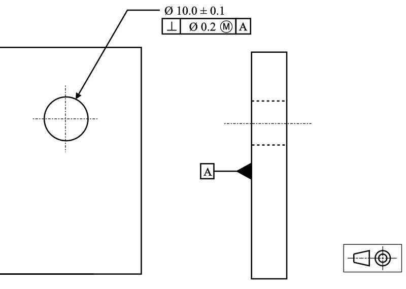
Common Surface Finish Symbols
The various symbols are used to indicate various surface finish standards and what they mean.
- =: Shows tool directionality of parallel marks made by cutting tools.
- ⊥: Indicates tool marks that run in a plane, at right angles to the surface being analyzed.
- X: Refers to cutting tool marks that cross each other in the material being worked on.
- M: Familiar with grooves created by polishing or lapping and these grooves may run in different directions.
- C: Shows concentric circular patterns on the outer skin.
- R: Concerns longitudinal grooves produced by cutting instruments and running in the same direction as the surface.
Achieving Different Surface Roughness Levels
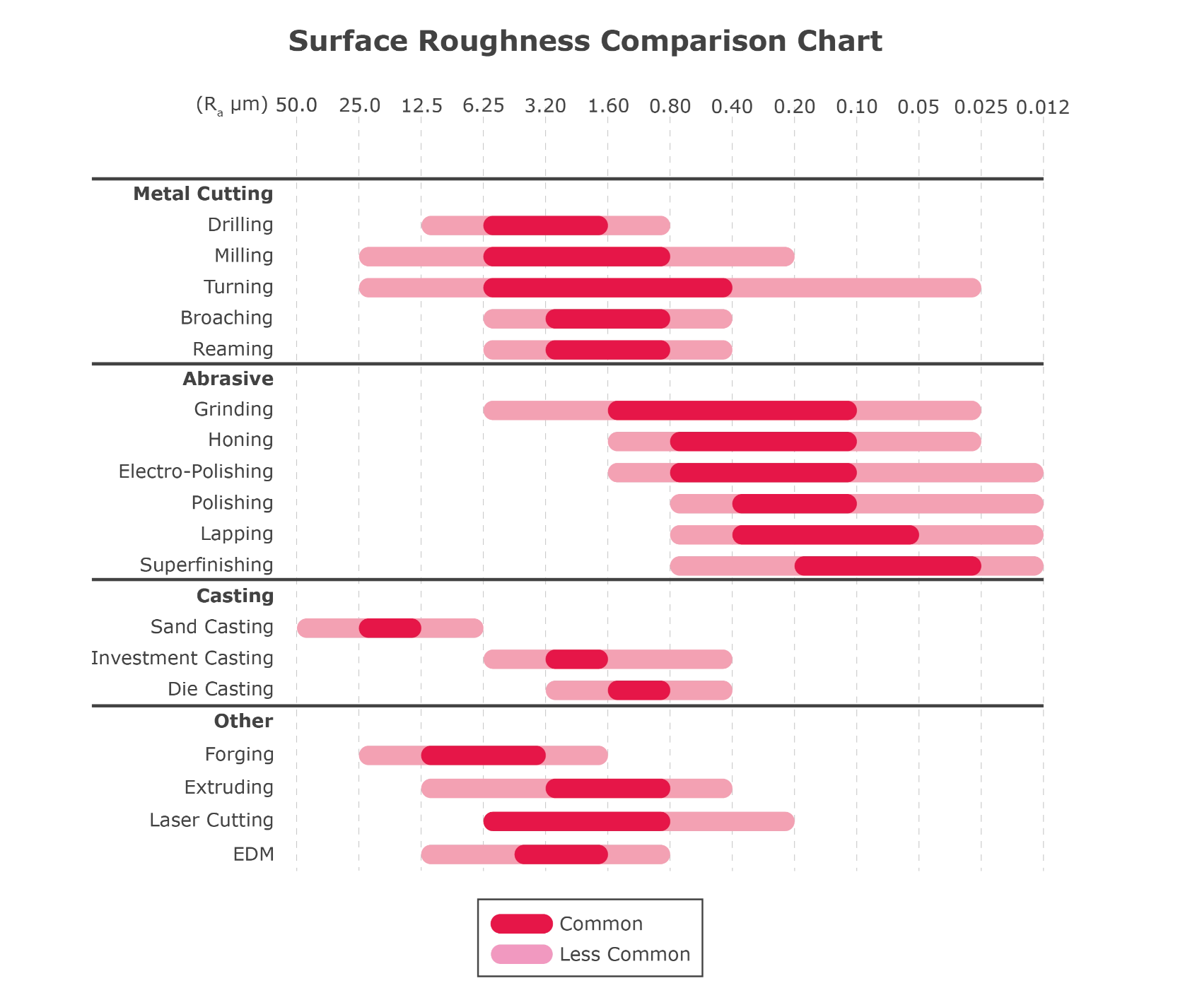
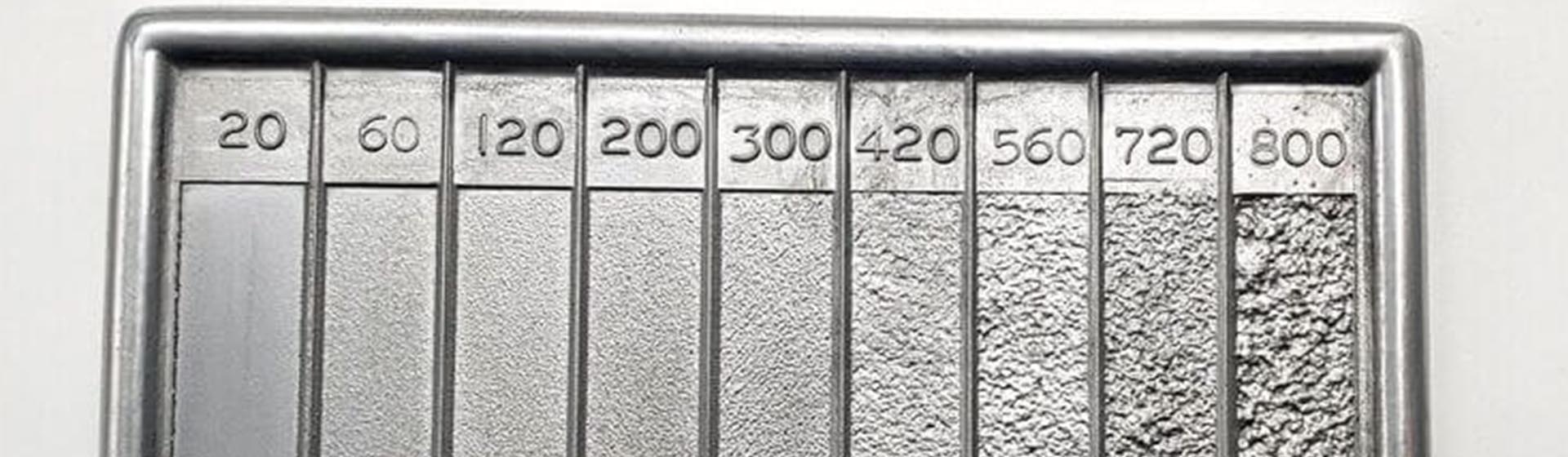
Surface Roughness Chart
Image Description: An illustration showing a surface roughness chart, highlighting different roughness values and their corresponding surface profiles.
Machinability, in particular, is a function of surface roughness. It has a direct effect on both the durability and efficiency of the manufactured part. Selecting certain roughness levels is not a gamble; it has to be well-planned and done to comply with standards like ISO 4287. These standards of range of Ra values are 25 μm to 0.025 μm, which are invaluable in all the manufacturing processes through the inclusion of CNC machining.
At Premium Parts, we provide four distinct surface roughness levels for CNC machining applications, each intended for specific operational requirements:
3.2 μm Ra
3.2 μm Ra is equivalent to a typical commercial machining finish. It has its surface somewhat more grainy and with spittle cuts, which makes it appropriate for most consumer uses. The machining process uses high speed and light feed rates, which ultimately produces a machined shiny surface, fast-running, and visually appealing. In the case of components that are likely to experience moderate stress, load, and vibration, the maximum recommended roughness is 3.2 μm Ra. Moreover, it’s sufficient for mating surfaces where low loads and slow velocities are expected.
1.6 μm Ra
At (1.6 Ra) this level, the artifact finish has only thin lines of the cutting instrument visible. This roughness is suitable for the components that need to be fitted accurately and the under-stress sections. It is effective in slow-speed and low-load operation but not optimal for high-speed rotating parts. Further, for those parts that are subjected to high levels of vibrations. To obtain this finish it is necessary to cut at a high rate of speed with fine feed and light cuts under carefully controlled conditions. In the case of standard aluminum alloys, this configuration increases the manufacturing cost by about 2.5% with further variation depending on the part complexity.
0.8 μm Ra
Ra 0.8μm Ra is well known as a valuable surface finish and is a significant challenge for manufacturing processes’ control. This level is necessary for stressed components like bearings. The improved surface finish helps to diminish contact resistance and wear. So, it’s specifically useful for components that are not frequently used and/or lightly loaded. The finish adds approximately 5% to the cost of standard aluminum alloys. However, the cost may rise for more complicated cross-sections.
0.4 μm Ra
Components under high tension or high RPM require specific surface finishes. The optimal finish for these applications is 0.4 μm Ra, which signifies the highest quality. Evaluating at this level of finish is challenging as it needs sophisticated technologies and precision process control. The exact requirements for such roughness should only be set if necessary because such a surface finish greatly tends to incur a higher cost of production, about 11%-15% for common aluminum alloys, and even more if the part is complicated.
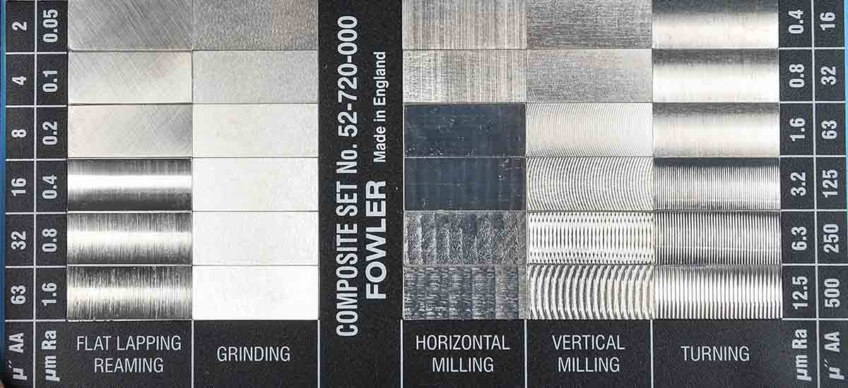
Surface Roughness (Ra) with Machining Techniques
Image Description: A chart showing surface roughness (Ra) values for different machining techniques. It compares the texture and smoothness of surfaces produced by various processes.
Surface Roughness Chart Cheat Sheet
The surface finish reference chart serves as an invaluable tool for understanding various surface finishes available in manufacturing.
Table: Surface roughness ratings & applications.
| Micrometers Rating | Microinches Rating | Applications |
| 25 | 1000 | Rough, low-grade surfaces from saw cutting or rough forging; suitable for unmachined clearance areas. |
| 12.5 | 500 | Rough surfaces result from coarse feeds and heavy cuts during turning, milling, and grinding techniques. |
| 6.3 | 250 | Produced by surface grinding and CNC drilling; ideal for clearance surfaces meeting specific stress requirements. |
| 3.2 | 125 | The roughest finish is recommended for parts subject to vibrations, loads, and high stress. |
| 1.6 | 63 | Good machine finish created under controlled conditions with fine feeds and higher speeds. |
| 0.8 | 32 | High-grade finish requiring close control, suitable for products with moderate load conditions. |
| 0.4 | 16 | High-quality surfaces are achieved through emery buffing or lapping; ideal for applications prioritizing smoothness. |
| 0.2 | 8 | Fine finish from lapping or honing, used where sliding components require minimal friction. |
| 0.1 | 4 | Refined surface finish utilized only for critical design requirements, common in precision instruments. |
| 0.05 | 2 | Most refined finish achieved through superior honing or buffing, ideal for precision gauge blocks. |
| 0.025 | 1 | Exceptional surface finish for sensitive applications, providing the utmost accuracy in measurement tools. |
Conclusion
Accurate surface roughness in today’s manufacturing environment is often a difficult and expensive proposition. Therefore, manufacturers must employ proper methods to achieve the right surface finish on fabricated parts. Consequently, they must understand the surface hardening capabilities of materials to achieve optimal surface finishing outcomes.
At Premium Parts, we provide all the surface finishing services that match the highest quality. The surface finish requirements are fully understood by our team of experts, who will ensure the best practice is used to reach the goals. Our services include full-dimensional inspection reports, which guarantee the results of your preferred specifications. We offer finishing options to our valued clients, including anodizing, electroplating, bead blasting, polishing, and many others.
As a quality and on-demand manufacturing company, Premium Parts can take your products to the next level. Contact us today for a free consultation. Our Engineers are always ready to help you.
FAQ’s About Surface Roughness
Q1. What does surface roughness mean, and why is it significant?
Roughness is a measure of the surface texture, the microscopic, high-frequency structure of surface features. It’s crucial in engineering since it determines the friction and wear of components, besides their performance in different applications and use.
Q2. How Can I Measure Surface Roughness?
Roughness parameters usually include Ra (Roughness Average) and Rz, Average Roughness Depth. These values are measured by contact or non-contact means, where the surface profile is analyzed to determine the texture.
Q3.What Factors Influence Surface Roughness Quality?
Determinants like machining processes, the tool condition, and the cutting parameters as the key consideration areas. These parameters directly influence the surface roughness quality. In addition, feed rates and cutting speeds, tool path planning, and finally the material properties, also play a vital role in achieving an optimum quality finish.
Q4. How does surface roughness affect component performance?
Some of the most appreciated surface roughness can dramatically change the component performance due to the changes in the friction, adhesion, and wear properties. For example, a finish of low roughness gives less friction and better lubrication, while a finish of high roughness provides better adhesion for any coating.
Q5. What are the Typical Applications for Various Surface Roughness Levels?
Surface roughness parameters are adjusted to different uses; for common consumer products, 3.2 μm Ra is used, and for high-performing parts, 0.4 μm Ra is employed. Applications include automotive, aerospace, and medical industries, where surface finish plays a key role in application performance and reliability.